
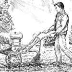
The proposed plow originated, one might say, from a shovel. One spring day on my garden plot, I was making furrows for planting root crops. The soil had been previously plowed, but I had to work bent low, and therefore suffered quite a bit. In the yard at that time, my first-grader grandson Igor was playing with the dog, and I called him for help. I tied the ends of a rope to the shovel’s socket, hitched myself up, and my grandson tried to hold the shovel at an angle so that it would push the soil out of the furrow. But he clearly didn’t have enough strength for such work: the shovel either jumped to the surface or buried itself in the ground so that I couldn’t move it further.
And here, along the way, the design of a soil-working device matured, which I literally made in a couple of free evenings from available materials. I even find it difficult to give this manual unit a specific name: whether it’s a furrow digger, a row cultivator-hiller, or a kind of ard. However, all these names would fully correspond to the functions performed by the plow.
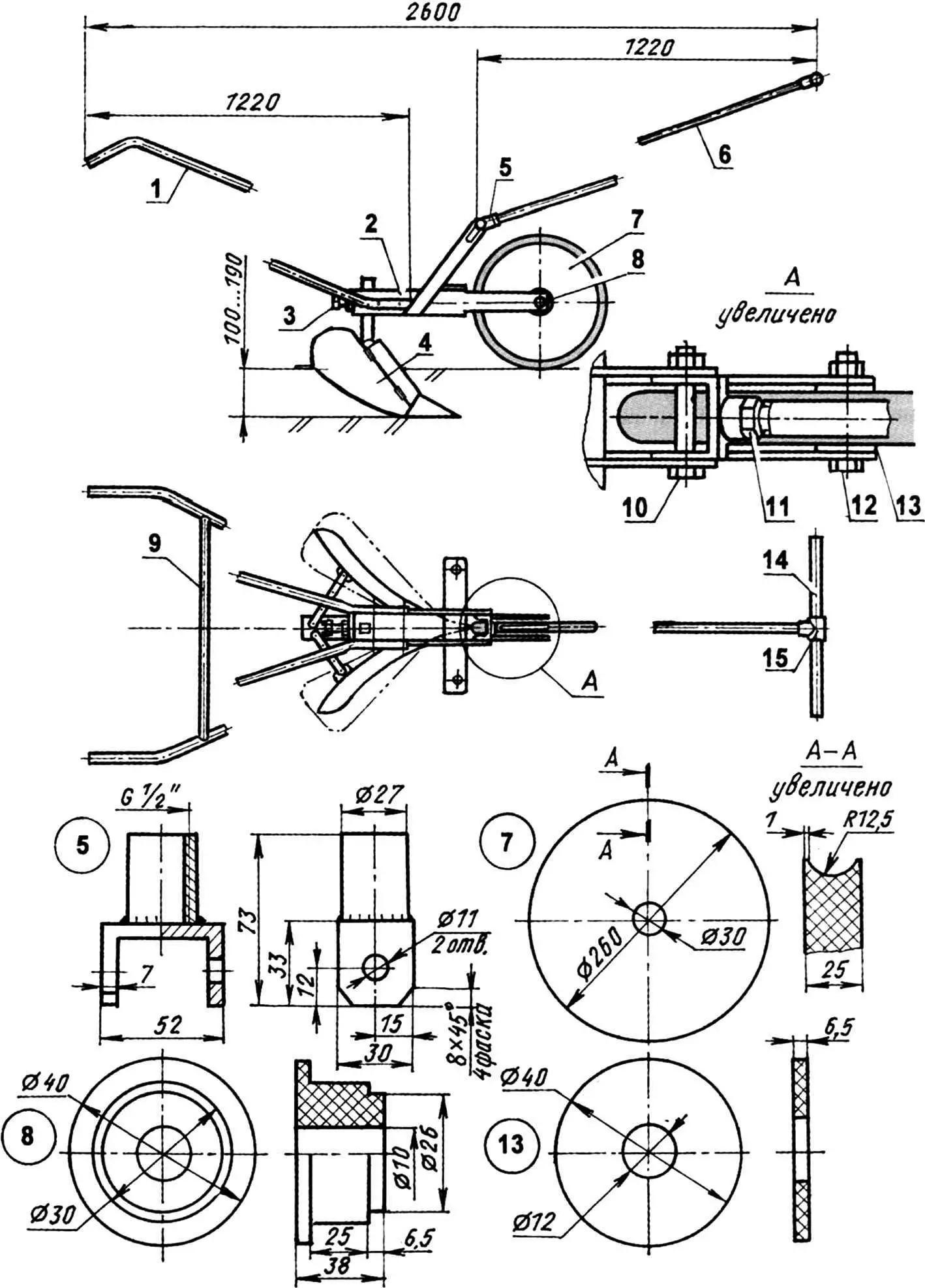
1 — handle (1/2″ pipe, 2 pcs.); 2 — frame-beam; 3 — plow post fixer (M10 screw); 4 — plow; 5 — hinge fork for attaching drawbar to frame; 6 — drawbar (1/2″ pipe); 7 — wheel; 8 — wheel hub-bearing (nylon); 9 — handle crossbar (1/2″ pipe); 10 — hinge axis (Ml0 bolt); 11 — lock nut (1/2″); 12 — wheel axis (M10 bolt); 13 — spacer washer (nylon, 2 pcs.); 14 — drawbar handle (3/4″ pipe); 15 — tee
For the frame-beam base, I used a piece of steel rectangular thick-walled pipe with a cross-section of 52x40x7 mm. In one part of it, I made a fork for the support wheel by cutting off two opposite (wider) walls. From the top, approximately in the middle, I welded a transverse crossbeam to the frame base and, in the same place, to the side walls — post-eyelets for connecting the drawbar. I welded the front outlet hole in the pipe-frame (at the beginning of the fork) shut so that soil wouldn’t get packed in there.
I also welded a plate to the rear hole, drilled a hole with a diameter of 11 mm in its center, and welded an M10 nut to the plate.
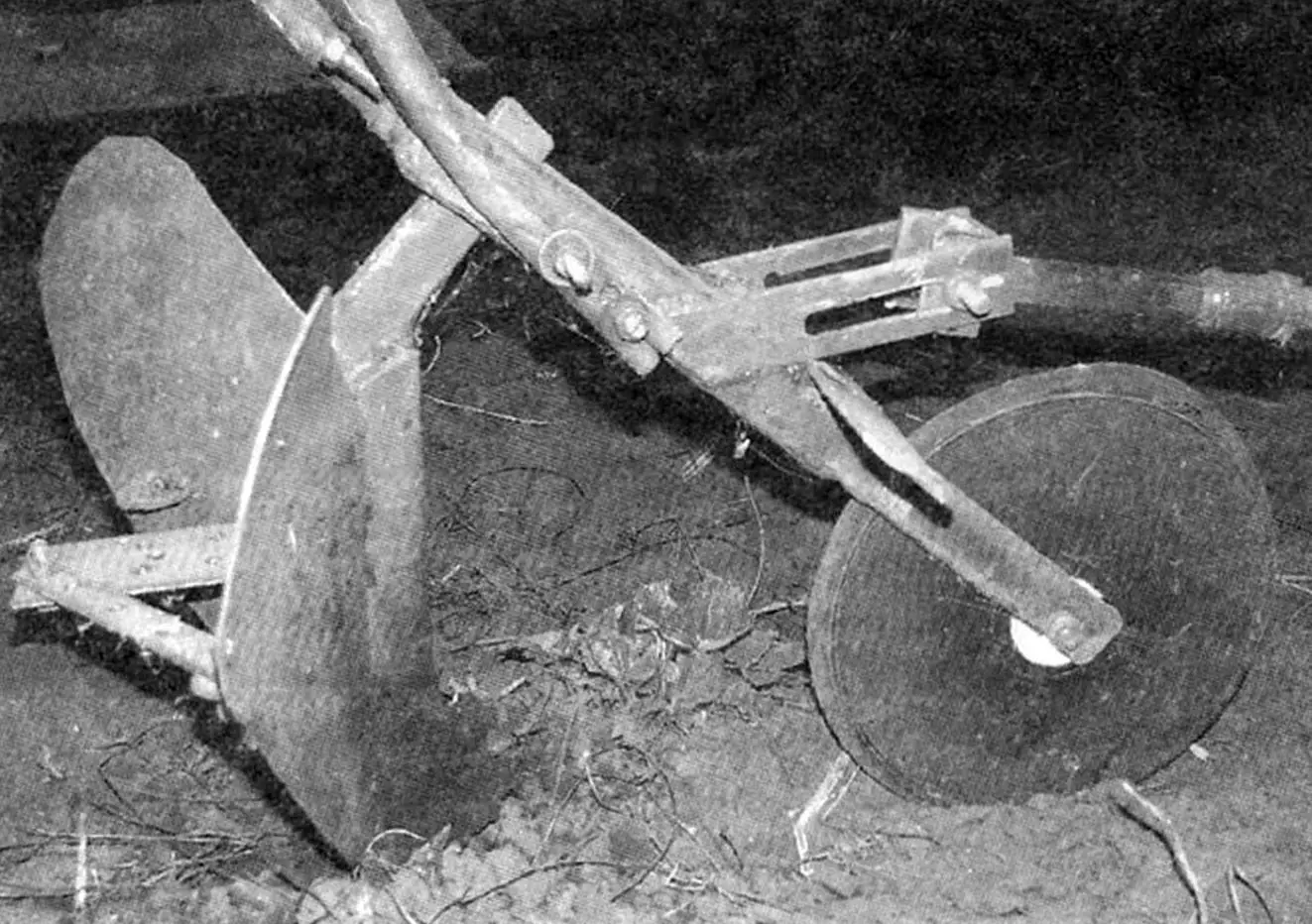
Also at the end of the pipe in the wide walls (upper and lower), I made a rectangular through hole 31×16 mm for the plow post, and in the side narrow walls — also through holes with a diameter of 10.2 mm — for M10 bolts for attaching the handles. I made two handles from half-inch water pipe; I chose their length according to my height, but bent them so that it would be convenient for both me and my grandson to operate the plow. I flattened the lower ends of the pipes, drilled holes in them corresponding to those made in the frame for their attachment. I wrapped the upper ends with several layers of electrical tape — got kind of handles. For rigidity, I later connected the handles with a welded crossbar from the same half-inch pipe (it’s not in the photo yet).
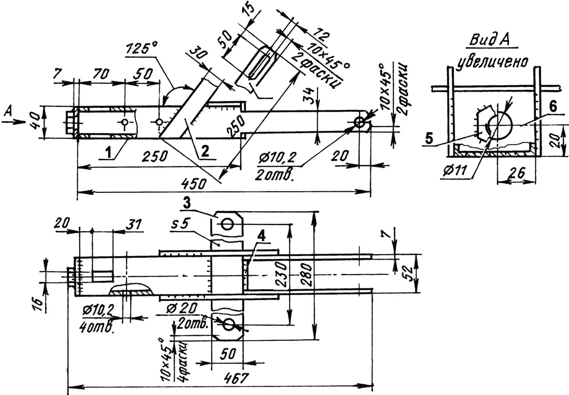
1 — base (steel rectangular pipe 52x40x7); 2 — post (steel sheet s5, 2 pcs.); 3 — crossbeam (steel sheet s5); 4 — front plug (steel sheet s7); 5 — M10 nut; 6 — rear plug (steel sheet s7)
I also made the drawbar from a piece of half-inch pipe, cutting corresponding threads on both its ends. I connected it hingedly to the eyelet-posts of the frame through a fork on an axis with lock nuts. The fork itself is from a short piece of the same rectangular pipe from which the frame base was made: I cut a channel from it. I welded a half-inch coupling to the wall of the latter from the outside. I used a long M10 bolt as the hinge axis. I screwed a tee with a through hole for 3/4″ onto the other end of the drawbar, ground down the thread in it, and inserted a crossbar — a pipe piece of suitable length and diameter.
I took the wheel from an old children’s bicycle, but used only the tire. I cut the disk from a 25-mm sheet of getinaks, turning a groove in its edge for the tire, and made a hole in the center for a nylon hub-bearing. I again used an M10 bolt as the wheel axis.
The main working element of the plow is its body, of which there can be many design solutions depending on the purpose. I had to make my own version, a symmetrical design — with two moldboards; it works like an ard — it doesn’t turn over the layer, but only pushes the soil aside. The installation angle of the moldboards can be changed depending on the furrow width or the distance between furrows during inter-row soil cultivation.
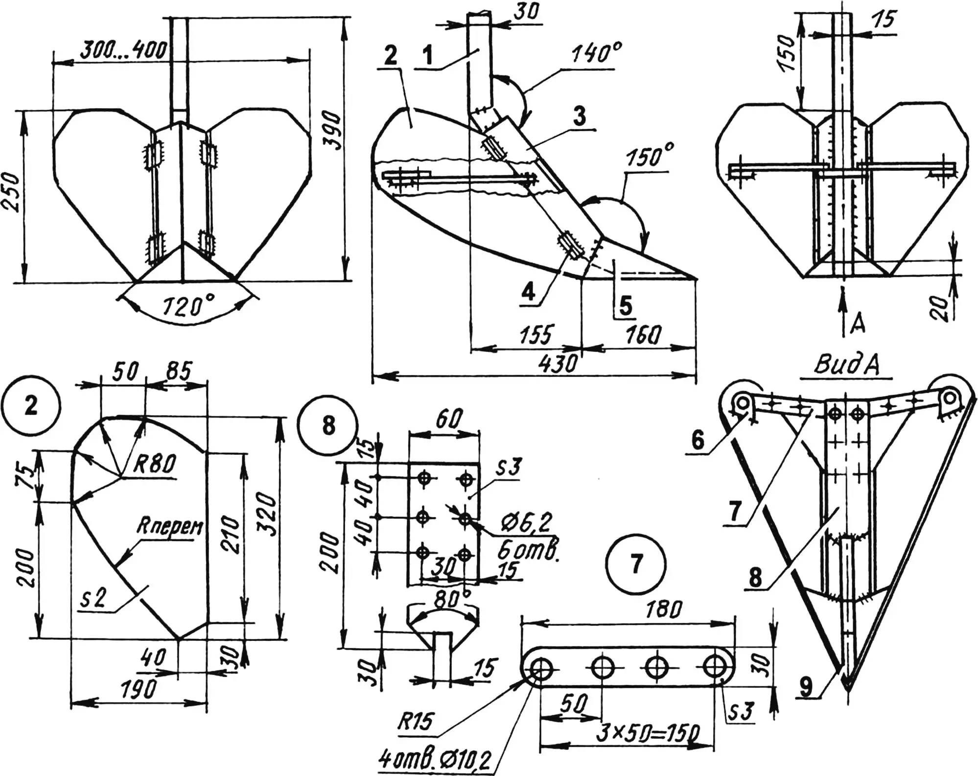
1 — post (30×15 rod); 2 — moldboard (s2 sheet, 2 pcs.); 3 — colter (steel 45, s3 sheet); 4 — hinge (card door hinge, 2 pcs.); 5 — share (steel 45, s3 sheet); 6 — eyelet (steel sheet s3, 2 pcs.); 7 — spacer (steel strip 30×3, 2 pcs.); 8 — thrust console (steel strip 60×3); 9 — plug (s3 sheet)
The post, colter, and share of the body are made as one part — their blanks are welded together. The post is of a broken configuration, from a 30×15 mm rectangular pipe (holes in it at the bottom and top are welded shut). The colter and share are made from 3-mm sheets of tool steel, bent into angles: the colter — with shelves 45×45 mm and an angle between them of about 80°, and the share with shelves at the base 85×85 mm (cut in front to a cone) and an angle between them of about 120°. Thus, the share turned out to be double-sided, like a sweep cultivator tine.
The moldboards of the tool are made from steel sheet 2 mm thick. In shape, although they resemble plow moldboards, they are almost flat, as they are not intended for turning over the soil layer.
The moldboards are connected to the colter hingedly — on welded ordinary card door hinges. A spacer device is made to set a certain angle between them. It consists of a console welded to the post with distributed holes and stops. Eyelets are welded to the rear sides of the moldboards — the stops are screwed to them and to the console with M4 screws. Each of the moldboards can be set at its own angle if necessary. The console, stops, and eyelets are made from steel sheet 3 mm thick. The body post is inserted into the rectangular hole of the frame and secured here with an M10 screw.
The reader will, of course, notice some non-fundamental differences in the plow design in the photographs and drawings. I note that the drawings show later, improved versions.
The plow can also be used in harness with a horse or on mechanized traction — with a walk-behind tractor or mini-tractor. For this, it is enough to attach traces or draft links to the ends of the crossbeam.
V. KURAKIN
Recommend to read
 “Silver” motor plow
The All-Union Competition “Small Mechanization”, held by the editors of the magazine “Modelist-Constructor”, has gained wide popularity among the creators of small-sized agricultural...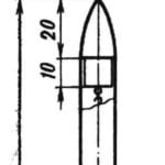 VICTORY – FOR DESIGNERS
In the autumn of last year in Tashkent was held the second personal championship of the USSR on flying sport, which was attended by 53 athletes from almost all the Union republics of our...
