With welding was not a problem — appreciate homemade “svarochnik”. With a number of turned work, as he tried to minimize that, things were more complicated. Of course, “the little stuff” performed by himself with the help of sandpaper, a drill and set of hand tools. Turning the main shaft and seats for the bearings had to charge u Turner from the neighboring machine shop.
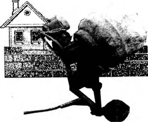
Kinematics (a) and layout (b) a self-made high-performance concrete:
1 —asynchronous motor (220 V, 1.2 kW, 900 rpm); 2 — a pulley lead (I) = 58 mm); 3 — belt drive, clip; 4— a pulley driven (compressor ZIL-130, D = 222); 5 — node of the intermediate shaft; 6 — a leading gear (g = 9); 7 — driven gear (the weld crown of the flywheel of the car GAZ-51 or “Moskvich”, g – 116); 8 node of the main shaft; 9 — a shaft rotating mechanism (steel pipe 40×6, L800); 10 — tank (iron 250 litre drums and steel wheel rim from farm machinery), 11—asterisk novorotor mechanism leading (z = 11, I = 25.4); 12 — the handle is improvised; 13— chain PR-25.4 mm drive roller; 14 — sprocket rotary mechanism, driven by a (z = 36, t = 25.4 mm); 15 — stopper (welded steel pipe 28×5, L64 with a steel finger d18, 1-80); a 16 — frame (steel pipe 45x45x4); 17 — pole (hexagon 42, L1000); 18 — Klondike (2); 19-drive-wheel hub (sprocket z= 25, t = 25.4 mm); 20 — rubber wheel (2 PCs); 21 node under engine swing frame; 22-the bearing of the rotary mechanism (welded steel tube 45×5, Ь46, 2); 23 — cosina-lodgment phase-shifting capacitors (steel rod 010,2). 24 — cosina (steel rod d15,2 PCs); 25 — blade warna (250x16x8 steel plate, 4 PCs.). The details of the poses. No. 2,3,6,11,13,14,19,20 from decommissioned machinery
Intermediate shaft Assembly:
1—intermediate shaft (steel rod d16); 2—nut M16 castle; 3 — sheave (compressor ZIL-130, D = 222); 4 — shaft rotary mechanism; 5 — bushing main shaft; 6 — base weld (steel area 40×45, L180,2); 7— the bearing housing (agricultural machinery 2); 8—bearing, 180502 (2); 9 — pinion (z = 9)
Node main shaft:
1 — shaft (steel 45); 2 — tank; 3 — a gear (toothed crown of the flywheel of the car GAZ-51 or “Moskvich”, z = 116); 4 — drive-wheel hub, weld-on (sprocket z = 25, t = 25.4 mm); 5 — bushing weld-in — housing tapered roller bearings (STZ or steel rough 96×15, L180); 6 — bearing 7307; 7 bearing 7306; 8 — castellated nut M24
The node under engine swing frame:
1 — plate under engine (steel sheet 125x84x4); 2 — finger (steel rod d18, L130) 3 — washer zaspirtovannaya (2); 4 — sleeve weld (steel pipe 28×5, L90); 5 — udasina-the cradle of the phase shift capacitors (steel rod d10, 2 pieces); 6 — shaft rotary mechanism; 7 — cheek (steel sheet 200x100x3, 2 PCs.)
Tank mixers made in several stages. Initially cut from the barrel blank with scalloped edges that are curled inwards to a diameter of 400 mm, and the joints prevail. As a bottom welded rim from a scrapped farm machinery. Unnecessary holes in it patched. Then welding the fixed ring gear of the flywheel of the engine of the GAZ-51 (centered!) main shaft, reinforced disc hub. The end of last drove under the roller tapered bearing 7307. Do not forget about the four Warnig blades from 8 mm steel plate.
According to the size of the tank and welded a frame from sections of steel pipe of square section. The result was the construction of two pillars United by a fork lift base. In front tabs, Yoshinari reinforced from 15 mm steel rod, wail sleeve (figure not shown) for fixing the axles of the wheels. To the heel at an angle of 20° to the horizontal attached to the pole — meter section of the hexagon 45. And to give the site extra durability, it has reinforced gussets.
On the racks by welding secured the bearings of the rotary mechanism. In addition, in the right of them drilled a hole that was waril axle sprocket with a homemade t-handle. Subsequently, on this same rack was placed and the sleeve stopper. Connection — welded, at the place of installation, the driven sprocket is placed on the shaft of the rotary mechanism.
At the other end of the shaft of the rotary mechanism fit three phase asynchronous motor (1.2 kW, 900 rpm). In home network 220 can be switched via a capacitor Bank with total capacity of 40— 80 UF (for it is the cradle formed by the two alosinae coupled with welded bushing and cheeks sub-frame) schemas that have been published in the journal “modelist-Konstruktor” (№ 8’95, 8’99, 10’2000).
Torque from the engine flows through the KPI-moremenu gear on the countershaft, bearing housings, which are mounted on the angled base. The latter are welded both to the shaft of the rotary unit and the sleeve, which is the case of roller bearings of the main shaft. In fact, it is a revolving structure under consideration (for a better understanding of the principle of its action) as three independent nodes.
Each has functional shaft with its pair of bearings. If the rotary unit is the bearings and the tube rotating in the bushings, then the intermediate — ball, and the main roller. Moreover, the application of the latter due to the need to withstand considerable axial stress during the loading and unloading of the tank.
Among other technical solutions, successfully working in a concrete mixer, a very soft “rubber” speed, reliability and stability of the structure, with the exception of its overturning by relying on the heel of the base frame. And, of course, the originality of the mechanism of a tension of the belt, where the desired effect is achieved by the weight of the engine, pulls the sub frame and non-slip V-belt transmission.
After ascertaining the advantages of my mixer, even in comparison with analogues of industrial manufacturing, the neighbors often asked to borrow it for a day or two. The special demand for the mixer — in the summer construction period.
Recommend to read SNAKES HANG GLIDERS On the pages of popular French children's magazine "Wife Anne" describes the two models of hang gliders, designed by Jean-Paul Movie and Christian Neuville. Wing Delta is an isosceles... COUNTRY-STYLE AND QUITE SUCCESSFUL The designer of this small truck — Yevgeny Nikitovich Yevsikov is already known to our readers from the publication «Plows, carries and even saws» (see «Modelist-Konstruktor» No. 5, 2002)....