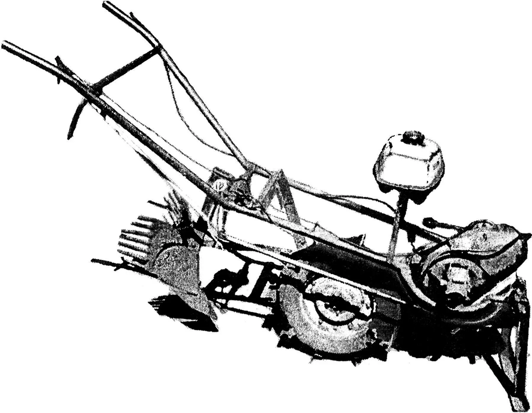
A story about all the machines and mechanisms created by amateur constructor Vasily Alekseevich SVERBIL from the village of Zelenchukskaya in the Karachay-Cherkess Republic cannot fit into one publication. It’s better to tell about them one by one. And we’ll start, perhaps, with the simplest thing the craftsman built—the “Elektronik” walk-behind tractor.
They say that the most convincing review of the walk-behind tractor was made by Vasily Alekseevich’s mother, Ksenia Petrovna, who said: “You, son, can take apart all your equipment by the nuts, even an airplane. But don’t touch this machine—it’s such a good helper around the house!”
“Elektronik” was also appreciated by other residents of the village. Many, seeing how quickly Vasily Alekseevich handles his and his neighbors’ plots with the help of the walk-behind tractor, began rummaging through their own sheds in search of old motor scooters. And now in the village gardens, about a dozen twins of “Elektronik” roar in the spring. The Cossacks copied the machine not at all because they had difficulty coming up with something similar themselves—there are plenty of craftsmen in the village. As they say, there’s nothing superfluous in this design—only what’s necessary. It’s simple, technological, and reliable, which, in fact, has been confirmed by years of its successful operation.
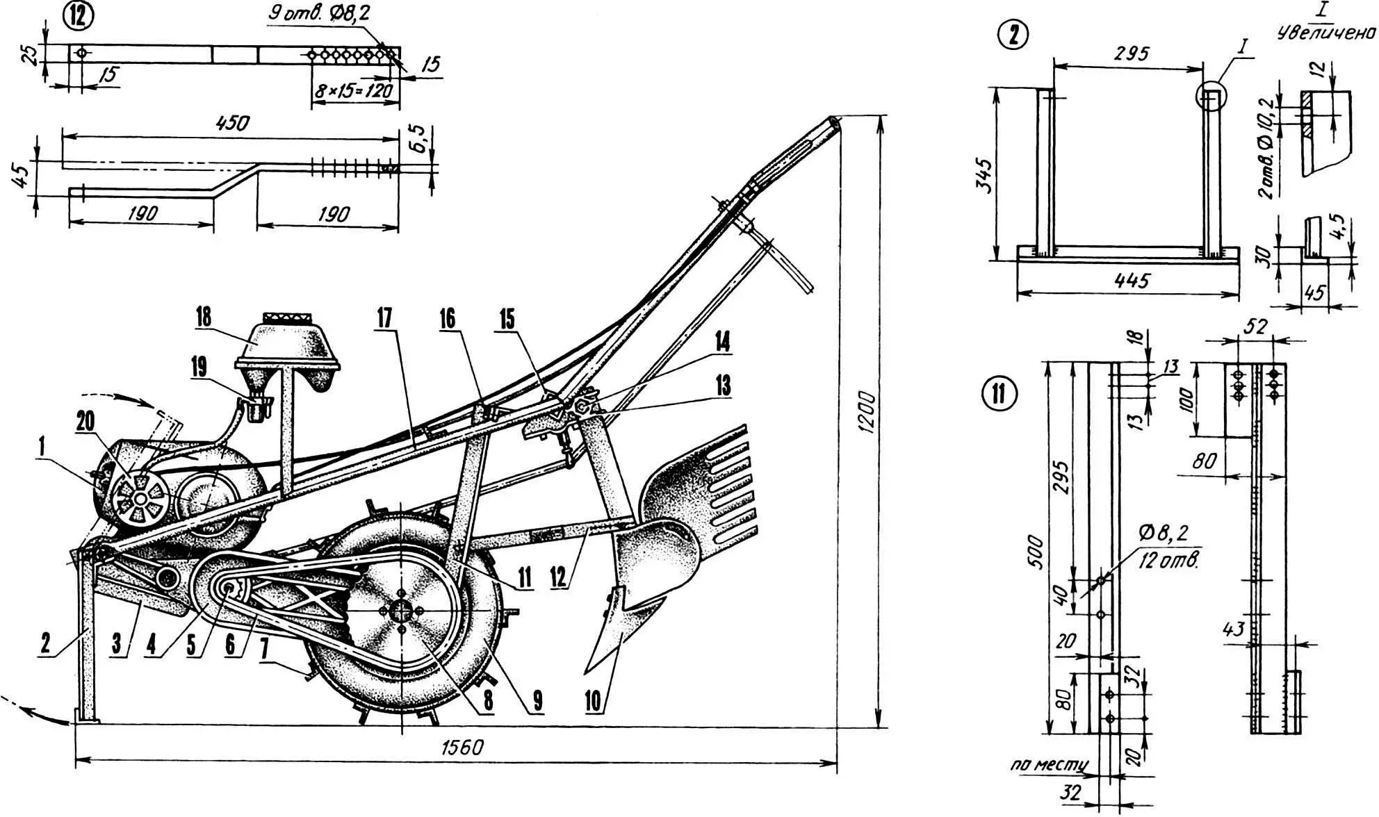
1 — engine (from “Elektron” motor scooter), 2 — stand, 3 — exhaust pipe resonator, 4 — power unit pendulum lever (from motor scooter), 5 — drive sprocket (z=8, t=19.05), 6 — drive chain (t=19.05), 7 — ground grip, 8 — driven sprocket (z=39, t=19.05), 9 — wheel (from motor scooter), 10 — cultivator, 11 — support (angle 40x40x4.5), 12 — curved bar (strip 25×6.5, L450), 13 — implement mounting bracket, 14 — M14 implement mounting bolt, 15 — stirrup, 16 — M8 support fixing bolt (2 pcs.), 17 — frame, 18 — fuel tank, 19 — filter-settler with valve, 20 — air filter (from “Pannonia” motorcycle).
Indeed, to make the walk-behind tractor, all that was needed was the “motor—wheel” power unit from the “Elektron” motor scooter (hence the name—”Elektronik”), several water pipes, and a few other small things. Moreover, the power unit was taken almost without modifications. Therefore, ideally, such an option is possible: a gardener arrives at his plot on a motor scooter with a trailer containing the frame, an additional wheel, and ground grips; transfers the “motor—wheel” to the frame and works the soil or plantings with the resulting walk-behind tractor. At the end, returning everything to its place, he goes home again on the motor scooter.
The modifications to which the power unit was subjected are very minor. First, the clutch mechanism cover was rotated 120° for more convenient connection of the control cable. Second, a 72 mm long arm with an eye for the control rod was welded to the gearbox segment—it became much easier to shift gears. Third, the intake pipe was straightened so that during inevitably sharp and steep tilts, the carburetor, equipped with an air filter from the “Pannonia” motorcycle, would work without interruption.
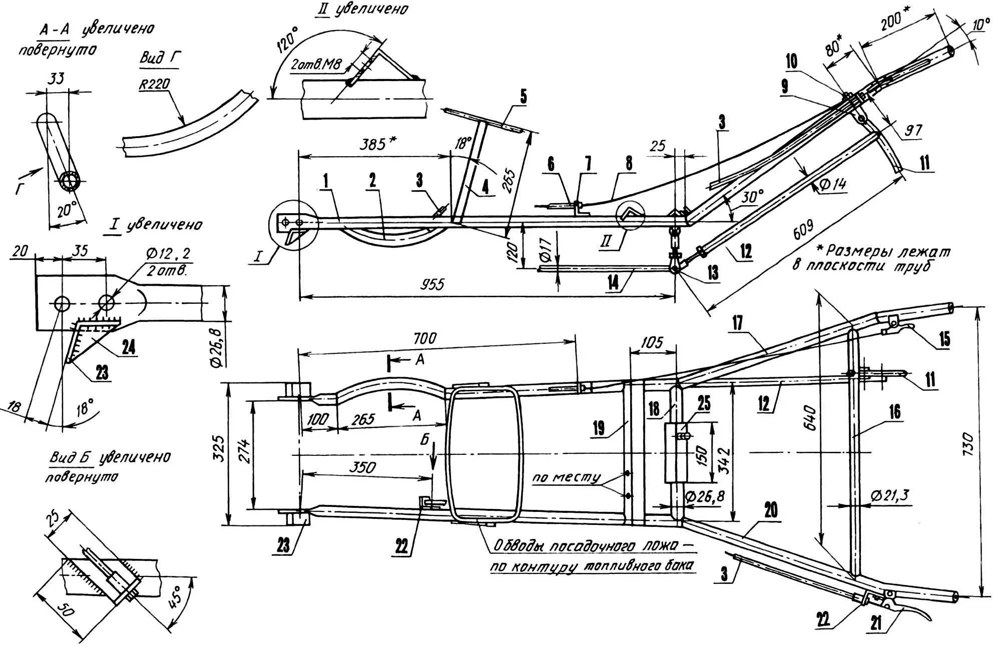
1,2 — left and right longerons (steel pipe 26.8×2.8), 3 — clutch cable sheath, 4 — fuel tank bed post (strip 20×4.5), 5 — fuel tank bed (rod Ø 8), 6 — throttle cable sheath, 7 — throttle cable sheath mounting bracket (angle 30x30x3), 8 — throttle cable, 9 — gear shift lever bracket, 10 — M8 bracket mounting bolt, 11 — gear shift lever (rod Ø 16, L150), 12 — rear rod (duralumin pipe 14x 1.5), 13 — rocker, 14 — front rod (duralumin pipe 17×1.5), 15 — throttle grip, 16 — spacer (steel pipe 21.3×2.8), 17, 20 — right and left control handles (steel pipe 26.8×2.8), 18 — cross member (steel pipe 26.8×2.8), 19 — crossbeam (angle 32x32x4), 21 — clutch lever, 22 — clutch cable sheath mounting brackets (angle 50x32x3), 23 — stop (angle 35x35x3), 24 — stiffening rib (steel sheet s3), 25 — welded slider (angle 35x35x3).
Since the walk-behind tractor’s operating mode requires different gear ratios, the drive and driven sprocket units were replaced with homemade ones. The first includes a hardened splined hub with a new drive sprocket welded to it and a tapered shaft with a flat for a 32 mm wrench. The tapered shaft neck is intended for mounting a belt drive pulley on it, going to the compressor. The latter (taken from the ZIL-130 automobile brake system) can be attached to the walk-behind tractor from the front and used for spraying plants or painting any surfaces (not shown in the figure). The driven sprocket unit has the same hardened hub, hub-body, and new driven sprocket, all welded together.
The power unit modified in this way is connected to a frame welded from water pipes 26.8×2.8 and partially 21.3×2.8 mm. The left longeron is made straight, the right one—curved, wrapping around the engine housing. At the front, both are flattened to form tips in which four holes are drilled: one pair of coaxial holes is intended for suspending the “motor—wheel” block, the other, together with angle stops—for a folding stand that holds the walk-behind tractor in a vertical position when parked.
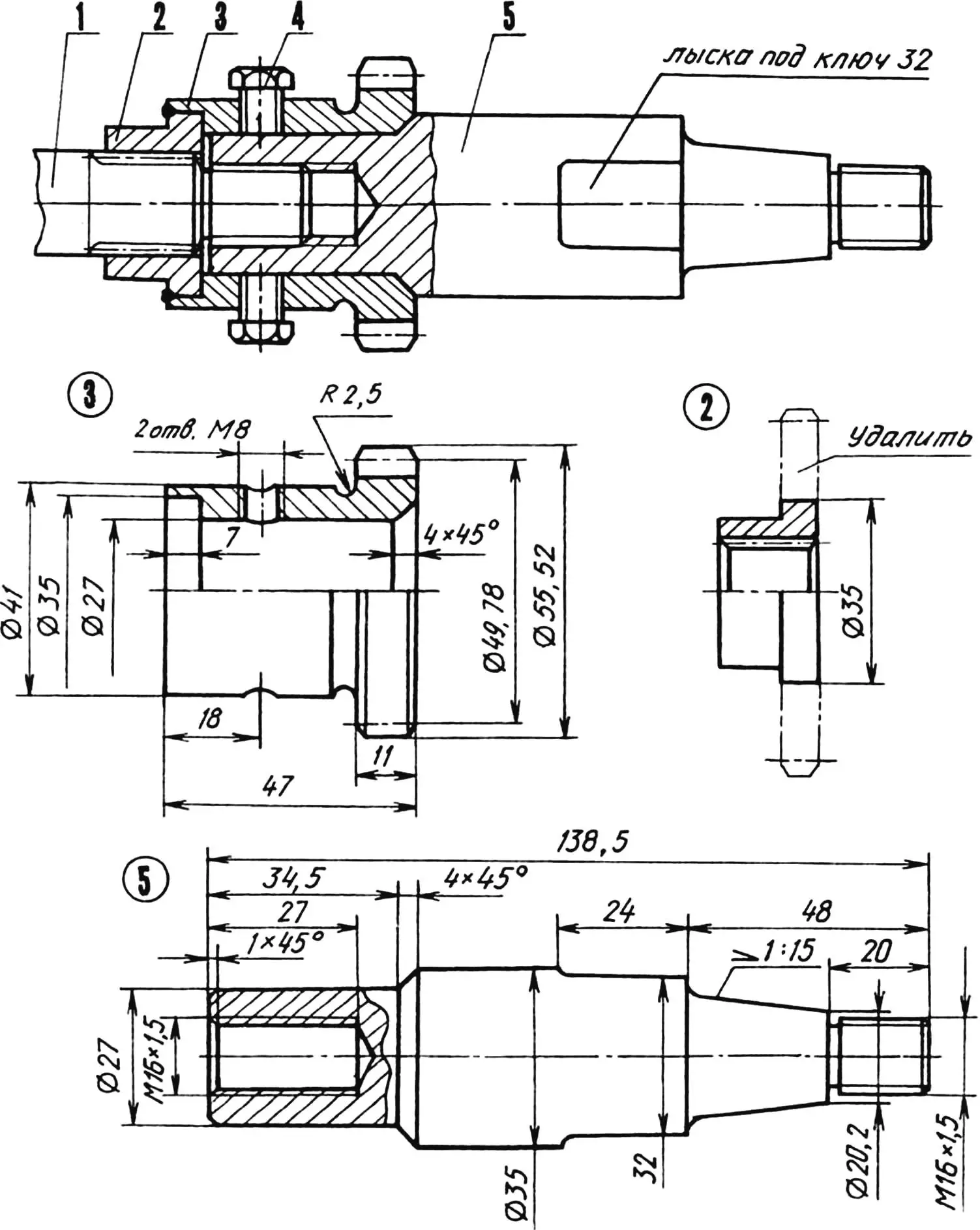
1 — engine output shaft, 2 — splined hub (from standard sprocket), 3 — drive sprocket (St5, z=8, t=19.05), 4 — M8 fixing screw (2 pcs.), 5 — drive shaft (St5).
Closer to the middle, fuel tank bed posts are welded to the longerons. The posts are slightly tilted back relative to the frame so that when the walk-behind tractor is parked or working, the tank (from the “Riga” moped) occupies a horizontal position and fuel is supplied without obstruction.
The longerons end with an angle crossbeam and a tubular cross member. A support is attached to the crossbeam, which gives rigidity to the walk-behind tractor structure, since together with the pendulum lever and frame it forms a force triangle (the upper rows of holes in the support are for adjusting the control handles to the operator’s height). The cross member serves as a mounting place for the implement bracket (more details about this unit—below).
1 — driven sprocket (St5, z=39, t=19.05), 2 — housing (St5), 3 — splined hub (from standard sprocket).
Behind the longerons, at a 30° angle to them, go the control handles, also made from water pipe. They carry: on the left—the clutch lever, on the right—the throttle grip. A tubular spacer is welded between the handles, to which a lever is screwed, connected by a pull linkage to the gear shift box segment (axial play in the linkage is taken up by adjusting the rear rod).
The ends of “Elektronik’s” handles don’t have grips (the operator holds onto bare metal—this is not very convenient, especially when plowing, when the walk-behind tractor is most wayward and unstable; it’s better to put on some grips, at least from a motorcycle handlebar).
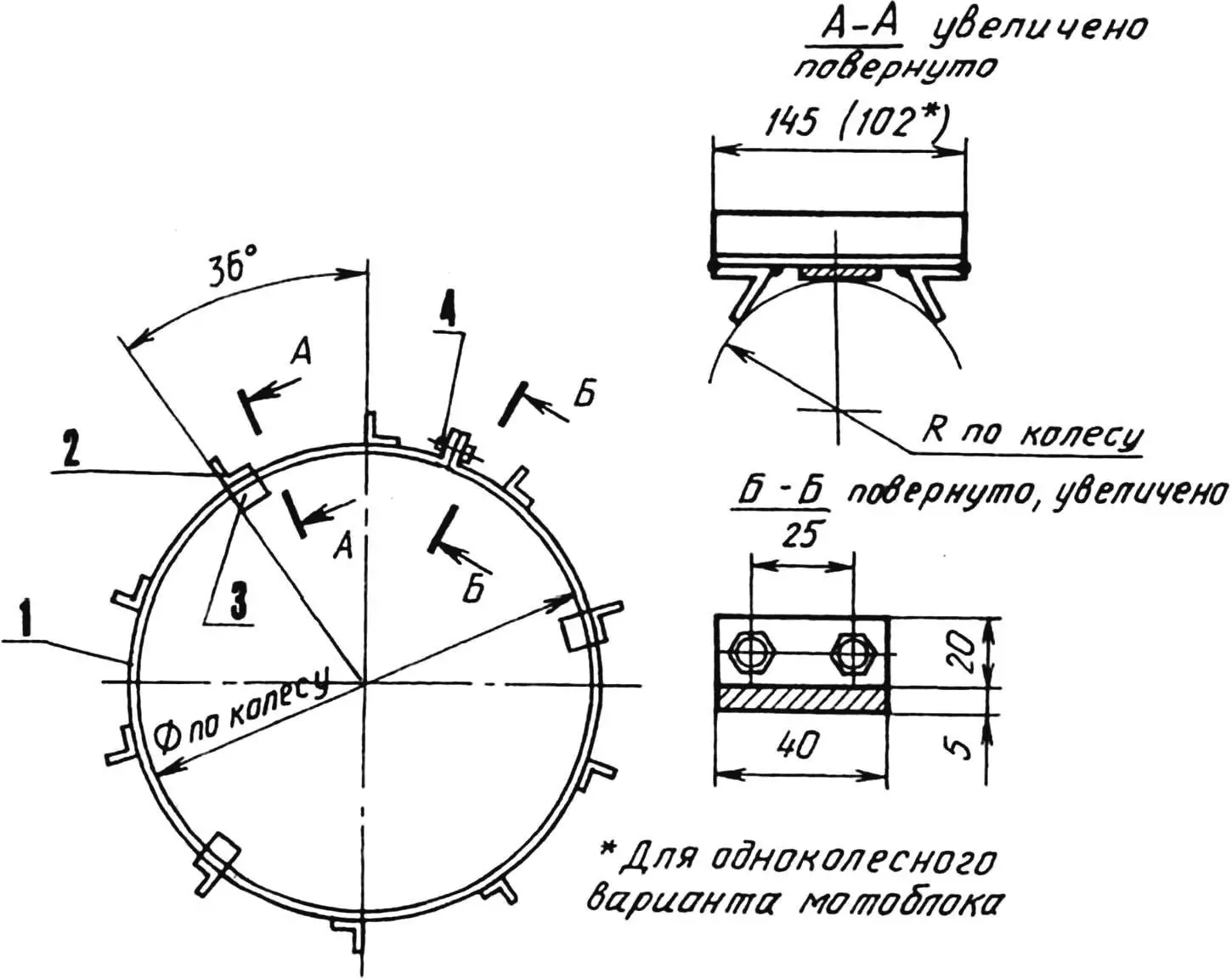
1 — rim (St3, strip 40×5), 2 — crossbar (angle 32x32x4, 10 pcs.), 3 — cheek (angle 32x32x4, 6 pcs.), 4 — M8 bolt (2 pcs.).
Now let’s return to the implement mounting unit. It consists of a slider and a bracket connected by a stirrup. The latter is bent from a steel rod 12 mm in diameter, with M12 threads cut on its ends. The slider is welded from two angles, equipped with an M10 stop bolt and put on the frame cross member during its assembly. The bracket is taken ready-made (from agricultural machinery); its body has a rectangular hole into which the shank, say, of a plow is inserted and held by an M14 bolt.
This unit design gives the implement three degrees of freedom, that is, allows its adjustment vertically (by the bracket’s M14 bolt) and within small limits horizontally and by angle—along and around the cross member axis (by the slider’s M10 stop bolt). The last adjustment—by angle—is stepped, its step is set by holes at the end of the curved bar, which rigidly fixes the implement in the selected position.
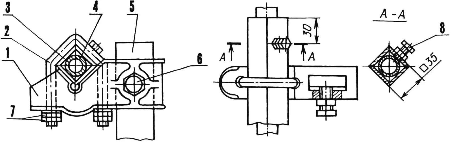
1 — bracket (from agricultural machinery), 2 — stirrup, 3 — slider, 4 — walk-behind tractor frame cross member, 5 — implement shank, 6 — M14 bolt with locknut, 7 — M12 nut and locknut, 8 — M10 stop bolt.
There are three implements for “Elektronik”: a plow, a cultivator, and a weeder. The first two are standard, without modifications. And they are used for their intended purpose. The last one, also used as a potato digger, is supplemented with tuber catchers—steel rods 10 mm in diameter, welded in three rows. For weed control, the shank of the modernized weeder is installed as it should be in such cases—vertically. Its tines perform their function—cut the roots of weeds, while the tuber catchers don’t work.
For harvesting, the shank is turned back to the maximum angle so that the weeder’s tines stand almost vertically and act like a shovel digging potatoes. The catchers, while sifting through clods of earth, capture the tubers and rake them into piles—all that remains is to collect them into bags.
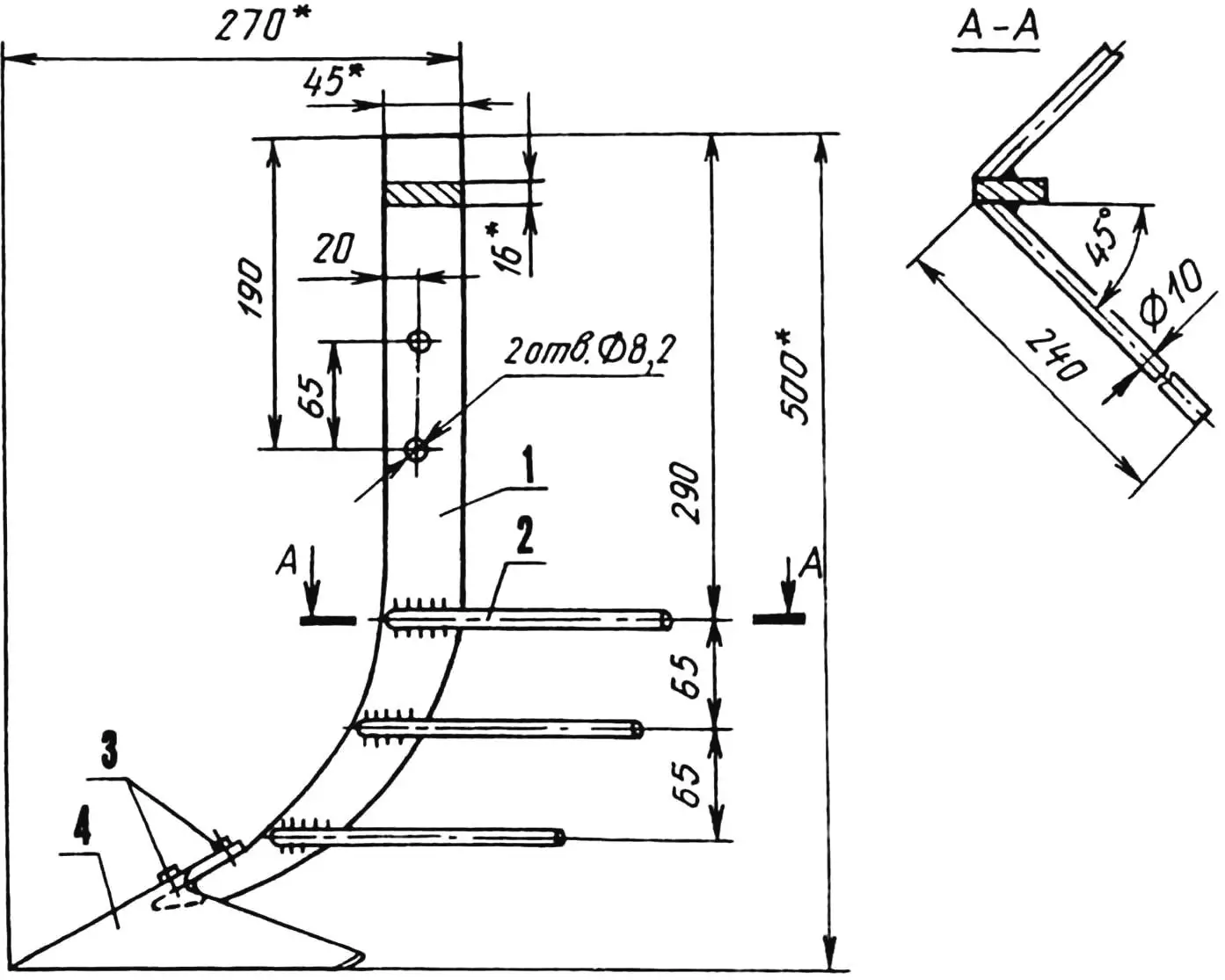
1 — shank, 2 — tuber catcher (6 pcs.), 3 — “nosar” mounting screws, 4 — “nosar”.
When working with implements, ground grips (of two sizes) are put on “Elektronik’s” wheels, assembled from strip rims, angle crossbars, and cheeks. For plowing, cutting and filling planting furrows, weeding and hilling plantings, a ground grip with 102 mm long crossbars is used (single-wheel walk-behind tractor variant). For digging potatoes—ground grips with 145 mm long crossbars (two-wheel variant). In this case, the wheel is removed, and the standard axle (together with ball bearings 204) is taken out, and a rear axle is installed in its place, made from three steel parts (shaft, driven sprocket, spacer bushing) and two bronze plain bearings. The latter are lubricated through an oiler screwed into a specially drilled threaded hole in the pendulum lever housing (between the bearings).
The two-wheel variant of the walk-behind tractor (with or without ground grips) is also used for transporting a cargo cart that can carry the operator plus six bags of potatoes—that’s about 400 kg (the cart design will be published later).
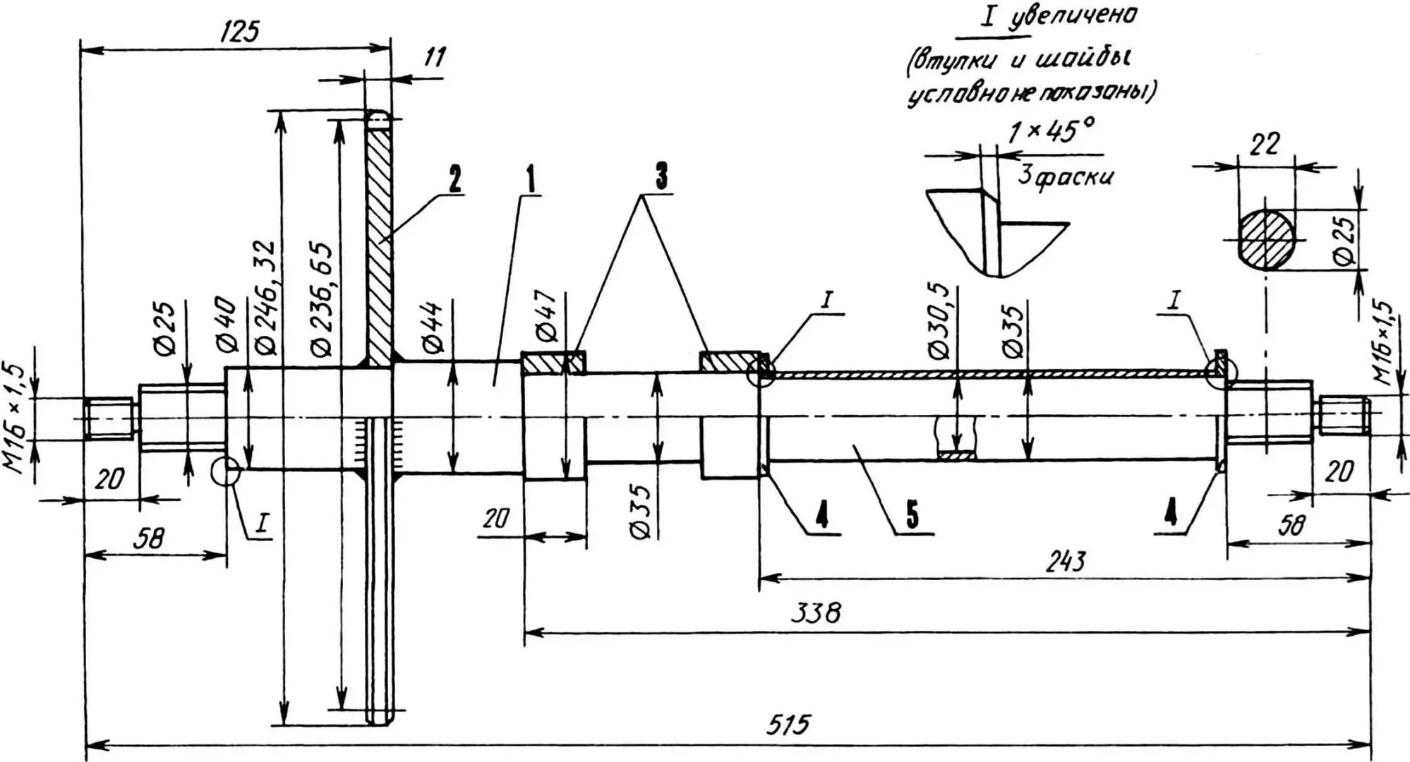
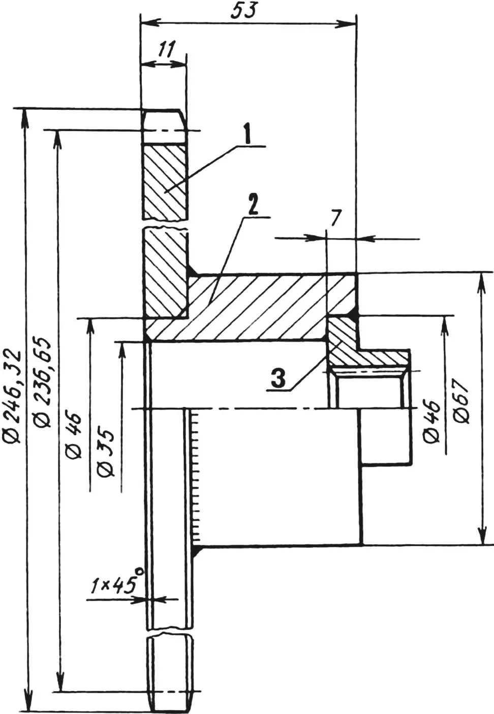
1 — driven shaft (St5), 2 — driven sprocket (St5, z=39, t=19.05), 3 — plain bearing bushings (bronze), 4 — washers (s2), 5 — spacer bushing (St3).
Since the motor scooter engine is quite undemanding, its maintenance comes down to periodic lubrication, cleaning, and refueling. It was started initially with a kickstarter, later a tractor magneto was installed.
Finally, it should be said that the soil on the banks of the Bolshoy Zelenchuk River is heavy, abounding in stones of various sizes—from fine pebbles to boulders. Stones, no matter how many you remove, seem to be born in the ground every year. Nevertheless, “Elektronik” has not dulled its plow on them, works reliably, and, I have no doubt, will still serve its creator.
A. TIMCHENKO
Recommend to read
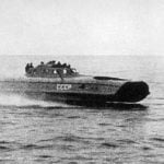 FLYING OVER THE WAVES
Hardly anyone would dispute that the twentieth century was for the engineers of gold in the literal and figurative sense. Discoveries and inventions made in those years will be used more... NOT RAISING DUST
To the broom lifted off the floor dust it can be equipped with its own humidifier. Take the flat plastic shampoo bottle, drill in the lid a few small holes, pour water and tighten on the...
