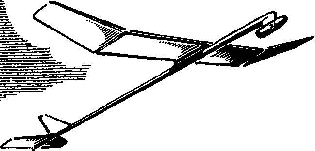
First the model of similar schemes appeared in the all-Union competition in 1982. With them were athletes from Moscow. But at the time of competition for soft raketoplana the type of wing”, Rogallo” they be not could. And further development of “hard” rocket gliders did not have. However, with the introduction in 1989 of a new category (S8 — rocket glider, which have not allowed separation of any elements of the design, including the engine block) this scheme has found a second birth in the category S4 (here design with soft wing is not allowed). In favour of the scheme say and world records set by V. Minakova and S. Ilyin, S. Ilyina at the training camp of the USSR team. The model we present to athletes rocketmodeler.
The fuselage of the rocket glider — tapered beam of plastic. It is molded on the mandrel of variable cross-section (maximum diameter 8 mm, the smallest is 3 mm), two layers of fiberglass with a thickness of 0.025 mm and one layer of carbon fabric with a thickness of 0.08 mm. After the treatment the mass of a beam with a length of 490 mm is 3 g.
At a distance of 132 mm from the edge of the bow glued the balsa insert with a length of 20 mm to enhance the attachment of the wing and the resin K-153 put the pad width of 8 mm and length 65 mm balsa.
The attachment consists of a Cup, bolts, gaskets and nuts. The Cup, which serves both the axis of rotation of the wing, are machined from aluminum. Particular attention is paid to the purity of the processing surface of the neck Ø 3 mm. Also made of aluminum grind the threaded bolt and nut M2. The gasket cut from a silicone tube Ø 4X1 mm.
 First the model of similar schemes appeared in the all-Union competition in 1982. With them were athletes from Moscow. But at the time of competition for soft raketoplana the type of wing”, Rogallo” they be not could. And further development of “hard” rocket gliders did not have. However, with the introduction in 1989 of a new category (S8 — rocket glider, which have not allowed separation of any elements of the design, including the engine block) this scheme has found a second birth in the category S4 (here design with soft wing is not allowed). In favour of the scheme say and world records set by V. Minakova and S. Ilyin, S. Ilyina at the training camp of the USSR team. The model we present to athletes rocketmodeler.