Ambrosia… This noxious weed, widespread in the southern regions of our country, causes a lot of trouble for farmers. Rapidly spreading in the open, it severely depletes and dries out the soil, and in fields it chokes out cultivated plants. Ambrosia is a frequent cause of poisoning in domestic animals, and in humans its caustic pollen can cause a serious illness — hay fever.
The hardiness and ability to quickly recover of ambrosia is so great that many chemical agents prove powerless against it, and those that the weed “can handle” are unfortunately not harmless to other crops. Mowing is also insufficiently effective, as after it the plant begins to bush heavily. Even cultivation does not give the desired result.
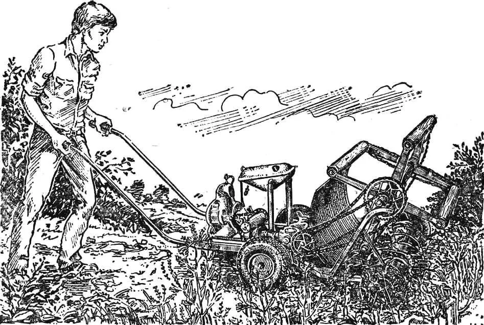
One solution to the problem was proposed by schoolchildren — members of the primary organization VOIR circle of Severskaya secondary school No. 44 in the Krasnodar Territory. They thoroughly studied the nature of ambrosia and, after conducting a series of experiments, established that the only reliable way to fight it is to pull out the plant along with the root. But doing this manually is difficult. And then the motorized weeder was born.
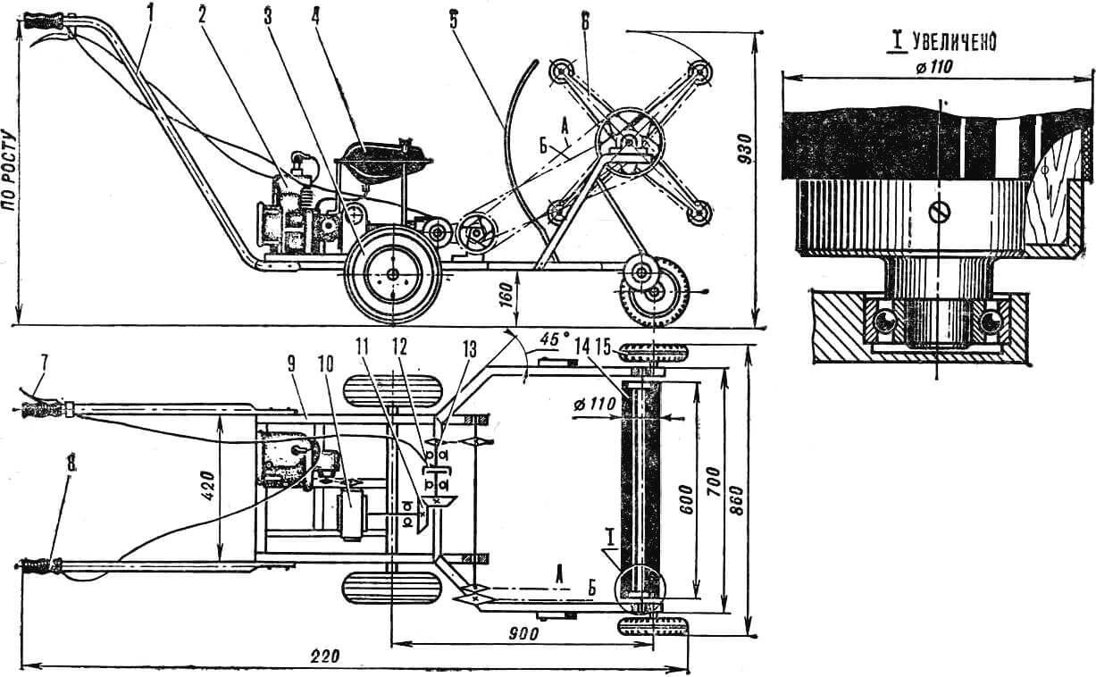
1 — handle, 2 — engine, 3 — rear wheel, 4 — fuel tank, 5 — shield, 6 — reel, 7 — clutch lever, 8 — rotary throttle handle, 9 — frame, 10 — worm reducer, 11 — bevel reducer, 12 — clutch, 13 — intermediate shaft, 14 — pickup drum, 15 — front wheel. A — reel drive chain, B — reel inner shaft drive chain.
Its operating principle is as follows. A small gasoline engine, through reducing bevel and chain drives, rotates the reel. It consists of two metal crosses with four wooden working rollers installed between them on bearings. The reel shaft is double; rotation is transmitted to the crosses through its outer tube, and from the inner shaft, using two chain drives, to the working rollers. In the lower part of the frame, a pickup drum is mounted on bearings — so that the minimum gap between it and the working rollers is about 1.5 mm. When the machine moves across a field overgrown with weeds, the working rollers tilt the plants, press their stems against the pickup drum and pull them out of the ground along with the roots.
The design uses an engine from the “Druzhba” chainsaw, reducers (worm with a gear ratio of 1:40, bevel 1:1) and a clutch from a decommissioned agricultural machine, sprockets and chains from bicycle and motorcycle equipment.
The frame is welded from 25X25 mm steel angles. It has supports for mounting the engine and reducers, fuel tank brackets, elements for attaching the front and rear wheel axles, intermediate shaft, shield and pickup drum. Inclined brackets — reel shaft supports — are fastened with bolts in longitudinal slots of the frame. This allows adjusting the gap between the working organs.
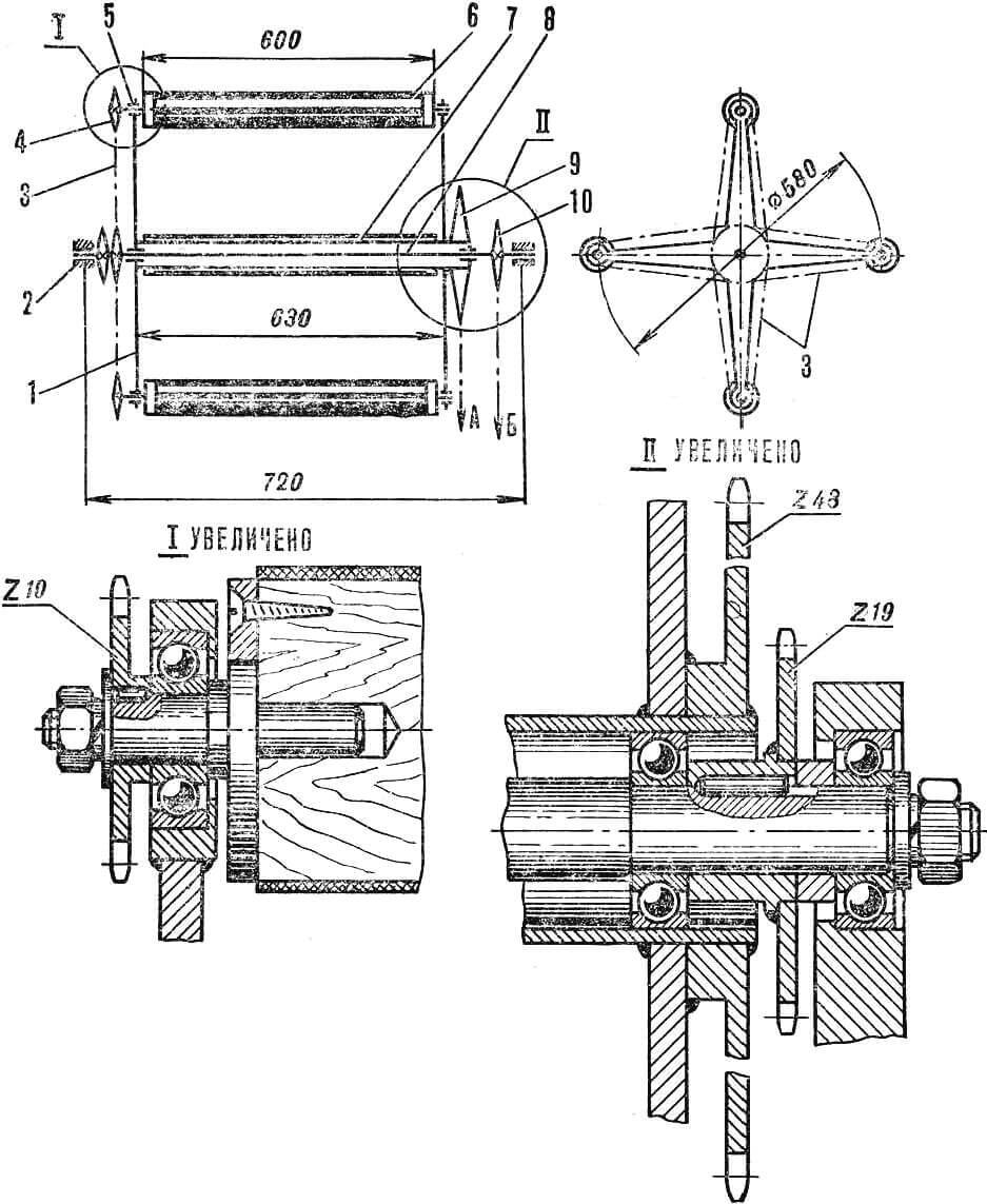
1 — cross, 2 — inner shaft bearing No. 203, 3 — working roller chain drive, 4 — working shaft sprocket (Z = 10), 5 — bearing No. 203, 6 — working roller, 7 — reel shaft, 8 — inner shaft, 9 — reel shaft sprocket (Z = 48), 10 — inner shaft sprocket (Z = 19).
The most labor-intensive part to manufacture is the reel. Four 8 mm thick steel strips are welded to a steel tube with an internal Ø of 40 mm on both sides. At the ends of the resulting crosses, in rings — segments of steel tubes — bearings No. 203 are installed — supports for the working rollers. The inner shaft of the reel is turned from a Ø 20 mm steel rod. Through two bearings No. 203, it rests on the frame brackets, and with two more supports the tube put on it — the cross shaft. The latter are rotated by a chain drive from the intermediate shaft: from a sprocket with z = 19 to a sprocket with z = 48, welded to the tube.
Another chain from a sprocket z = 32 on the intermediate shaft to a sprocket z = 19 rotates the inner shaft. At its opposite end, two more sprockets z = 19 are rigidly fixed. Each of them drives two working rollers with its chain.
The pickup drum and working rollers are turned from hard wood, covered with sheet rubber and mounted in bearing units using metal flanges. The cup-shaped flanges of the pickup drum rest with their pins on bearings installed in the frame brackets.
The transmission gear ratio and drive kinematics ensure, at the engine’s rated mode, rotation of the reel shaft at a frequency of 30 rpm, and the working rollers — about 100 rpm in the same direction.
Field tests of the motorized weeder showed excellent results. It turned out to be reliable and effective. Some design flaws were also revealed: the base is too long, the lack of swivel wheels and motor drive on the wheels complicates control. It is useful to equip the machine with a conveyor for removing pulled plants, a spring damper for the reel bracket, and install chain guards. We hope that those interested in the weeder will take our experience into account and create a more perfect mechanism.
N. OBREZHA
Recommend to read
 HOME SERVICE TIME
Hoping to equip the apartment "talking" for hours, tried to collect an acceptable design using standard domestic circuits. But once faced with the complexities of the "firmware"... THE SOURCE OF LIVING WATER
Spring, source, key all of these names refer to the mysterious place where no one knows where from under the earth breaks a timid trickle of clean and cool water. All peoples have always...
