How a snowmobile (motornart) differs from a motorcycle is clear to anyone familiar with these vehicles: mainly, the former is tracked and intended for travel on snow, while the latter is wheeled and for ground travel. In terms of comfort they are alike — both are open, although motorcycles are used mostly in warm weather and snowmobiles in cold and even severe winter.
As the table in this article (from the Buran snowmobile operating manual) shows, even a modest vehicle speed, especially into the wind, greatly increases cooling of the rider.
Therefore the idea of adding a wind-protected and, where possible, heated cab to the Buran snowmobile was not only natural but almost obvious.
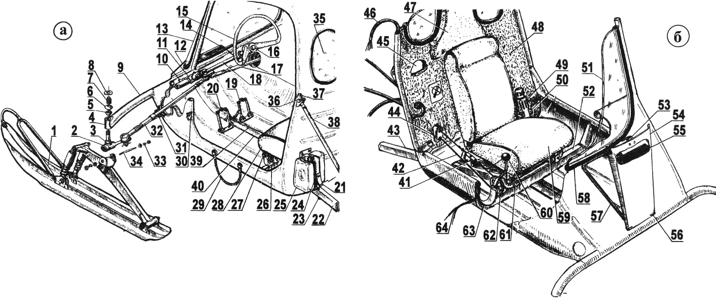
1 — reinforcement (2 pcs.); 2 — shock absorber (2 pcs.); 3 — swing arm (2 pcs.); 4 — crossbeam; 5 — service hatch cover; 6 — door; 7 — windshield (acrylic sheet s4); 8 — wiper; 9 — half steering wheel; 10 — headlamp control lever; 11 — headlamp; 12 — cab; 13 — side window (acrylic s4, 2 pcs.); 14 — rear view window (acrylic s4, 2 pcs.); 15 — control cables; 16 — power cable with connector; 17 — heater fuel tank; 18 — footboard (2 pcs.); 19 — tie rod (2 pcs.); 20 — subframe console (2 pcs.); 21 — brace (2 pcs.); 22 — snowmobile bumper; 23 — Buran motornart; 24 — motornart seat back bracket; 25 — cab seat; 26 — rubber boot; 27 — door hinge (2 pcs.); 28 — steering tie rod (2 pcs.)
Several Buran conversion options were considered at first. One was to cover the entire snowmobile with a single cab. Such a cab would require light yet strong materials; otherwise vehicle mass would rise sharply, the centre of gravity would move up, and already modest stability would worsen.
A second option was a two-seat forward cab with the passenger beside the driver. That too was rejected because of the cab’s mass — engine power might be insufficient in some on- and off-road situations.
1 — outer cab skin (plywood s3); 2,9 — filler (foam); 3,8 — inner skin (plywood s3); 4 — wire staples; 5 — cab frame tube; 6 — seal (foam rubber); 7 — self-tapping screw; 10 — outer door skin (plywood s5); 11 — door frame tube
The plan was a single-seat cab on “dudki” (auxiliary skis) with a hinged joint to the Buran. That was not final. The dudki had to go — they do not allow enough speed. A hinged module joint was also dropped: the joint could not be built in a home workshop, and no other fabrication route appeared. Such a hinge would also hurt handling in turns on slick snow.
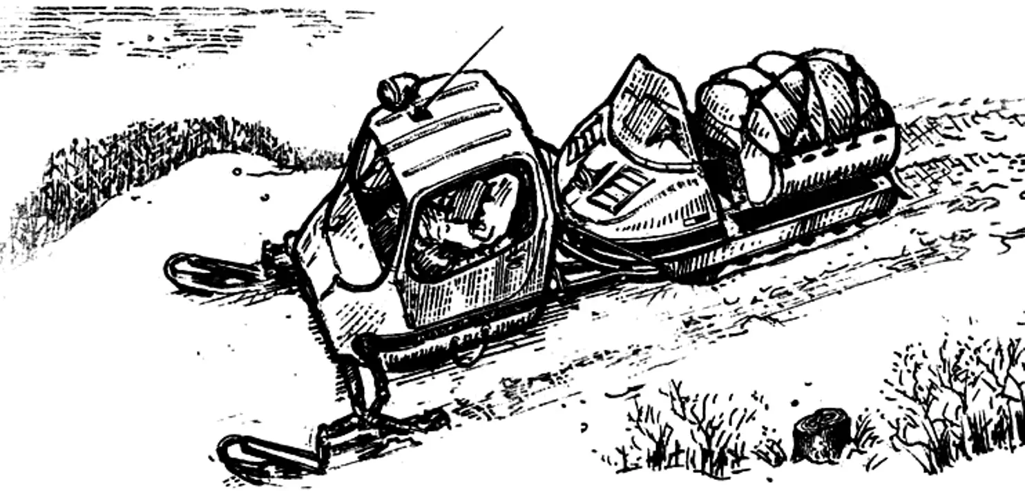
The final choice (largely a compromise) was a single-seat, two-support ski cab in tandem ahead of the pusher snowmobile, with rigid coupling between modules.
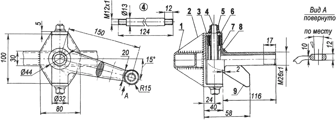
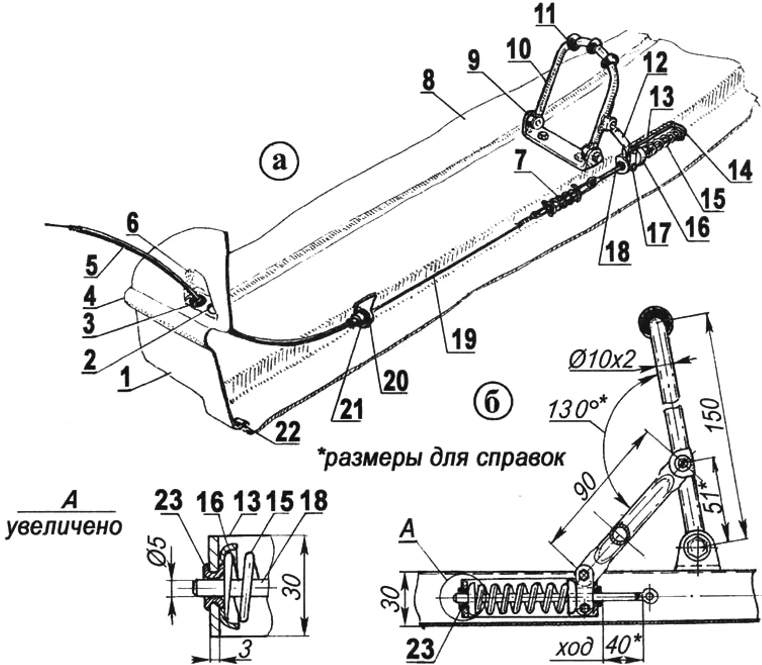
1 — welded kingpin bushing (tube Ø45×6, L80, 2 pcs.); 2 — crossbeam (tube Ø60×3); 3 — bracket for snowmobile reverse-reducer shift lever; 4 — heater shelf; 5 — steering shaft bearing cup; 6 — heater exhaust pipe stub; 7,8 — windshield and rear-view window frames; 9 — gusset with sphere for lamp ball mount; 10 — cab rear wall (steel sheet s1.8); 11 — lightening holes; 12 — upper fork; 13 — brace (tube 22×1); 14 — lower fork; 15 — pin (M8 bolt); 16 — subframe console (tube Ø20×40×3 mm); 17 — subframe rear gusset; 18 — fork (steel sheet s3); 19 — welded nut (M8, 2 pcs.); 20 — subframe cross member (tube Ø20×40×3 mm); 21 — cab floor (steel sheet s1.8 mm); 22 — door hinge half (2 pcs.); 23 — brake pedal bracket; 24 — Ø100 hole for steering tie rod (2 pcs.); 25 — throttle pedal bracket; 26 — steering gear bracket; 27 — connector hole (male); 28 — lug tab (steel sheet s4); 29 — cotter pin Ø3; 30 — subframe front gusset (steel sheet s3); 31 — bracket (steel s8); 32 — vent holes; 33 — tie tube (Ø27×3); 34 — locknut M16×1.5; 35 — tie upper fork; 36 — special bolt M12×1; 37 — frame tubes (Ø27×1.5); 38 — seat pull rod; 39 — bolt M16×1.5
The emphasis was on minimal changes to the snowmobile while keeping use without the cab possible. When cab and snowmobile (CS) work together, the handlebar with shaft and the guide ski are removed from the Buran and stowed in the cargo bed. The cab can then be detached fairly quickly, controls restored, and the snowmobile used alone in normal mode.
The «Kompromiss» tandem can be operated as: 1 — driver + cargo in bed (main); 2 — driver + two passengers on the motornart seat; 3 — driver + passenger and cargo in bed (extreme). The mode is chosen for actual conditions.
1 — ski; 2 — steering knuckle; 3,5 — bearing 746905; 4 — welded bushing; 6 — spherical washer (2); 7 — special nut M26×1/M30×1; 8 — locknut M30×1; 9 — crossbeam; 10 — steering gear bracket; 11 — steering gear (from S3D); 12 — service hatch cover (dural); 13 — windshield; 14 — steering shaft bearing cup bracket; 15 — half steering wheel Ø400; 16 — engine stop button; 17, 32 — steering tie rods (from S3D); 18 — steering shaft; 19 — throttle pedal; 20 — brake pedal; 21 — clamp; 22 — left cab subframe console; 23 — fuel tank mount (M6 nut); 24 — rubber gasket; 25 — heater fuel tank; 26 — seat hoop; 27 — hoop mount (M10 bolt); 28 — seat (from S3D); 29 — flexible footboard (cable Ø10); 30 — door hinge half (2 pcs.); 31 — boot; 33 — M12×1 nut with spring and flat washers (2 sets); 34 — swing arm axle (M12×1 stud); 35 — rear view window (2 pcs.); 36 — special bolt M10×1; 37 — upper fork; 38 — brace; 39 — throttle cable (Ø2); 40 — brake cable (Ø3); 41 — turnbuckle; 42 — reverse shift cable; 43 — right subframe console; 44 — lightening hole (2 pcs.); 45 — cab rear wall; 46 — interconnect cable to upper switch panel; 47 — headrest pad; 48 — insulation (felt sheet s5); 49 — fire extinguisher; 50 — extinguisher holder; 51 — windshield; 52 — frame cross member; 53 — spring latch; 54 — service hatch cover; 55 — pocket for emergency kit; 56 — hatch hinge (2 pcs.); 57 — rim with rubber seal; 58 — windshield rubber seal; 59 — seat; 60 — snowmobile reverse-reducer shift lever; 61 — fork; 62 — pulley Ø125; 63 — heater shelf; 64 — wire to engine «Stop» button
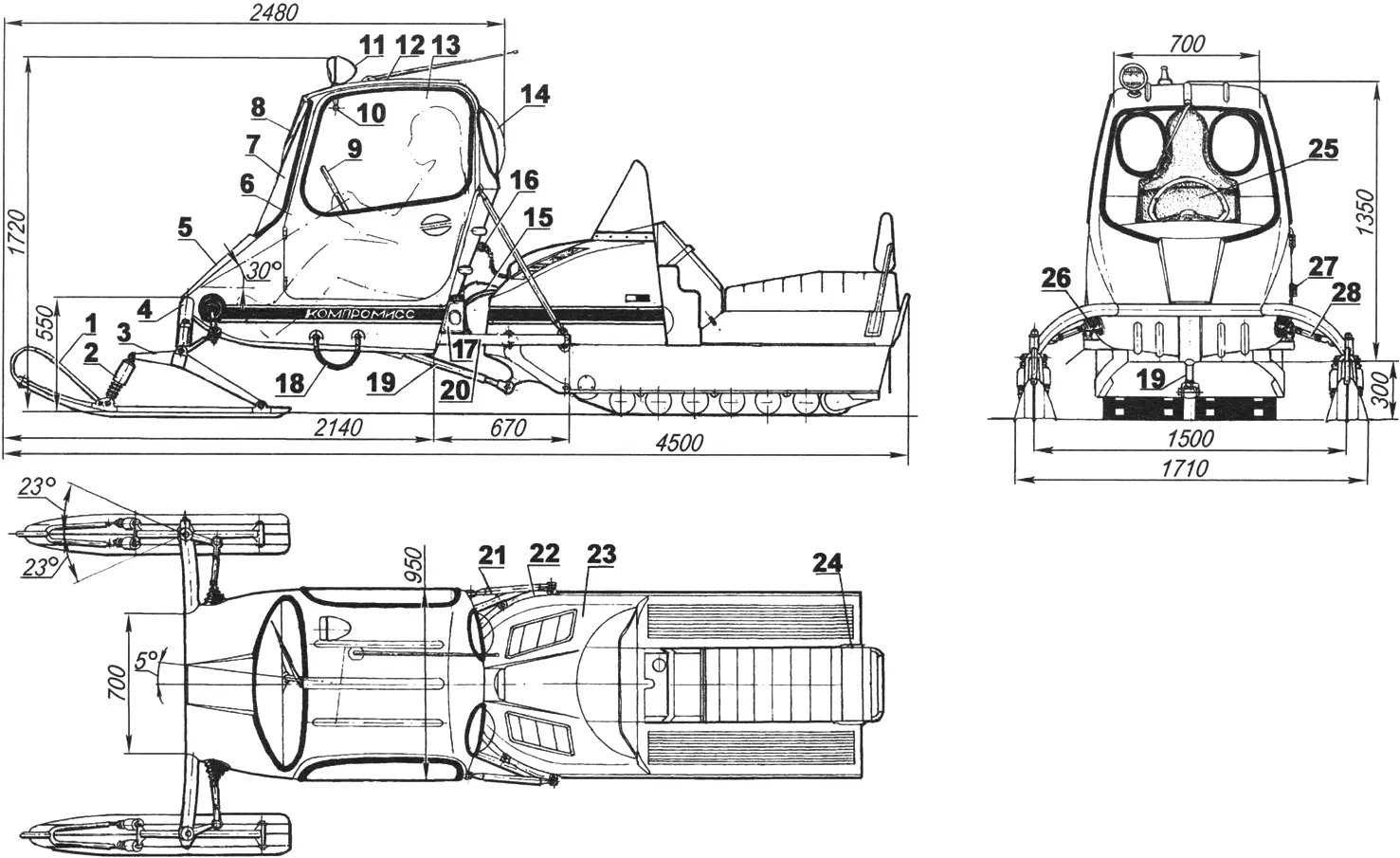
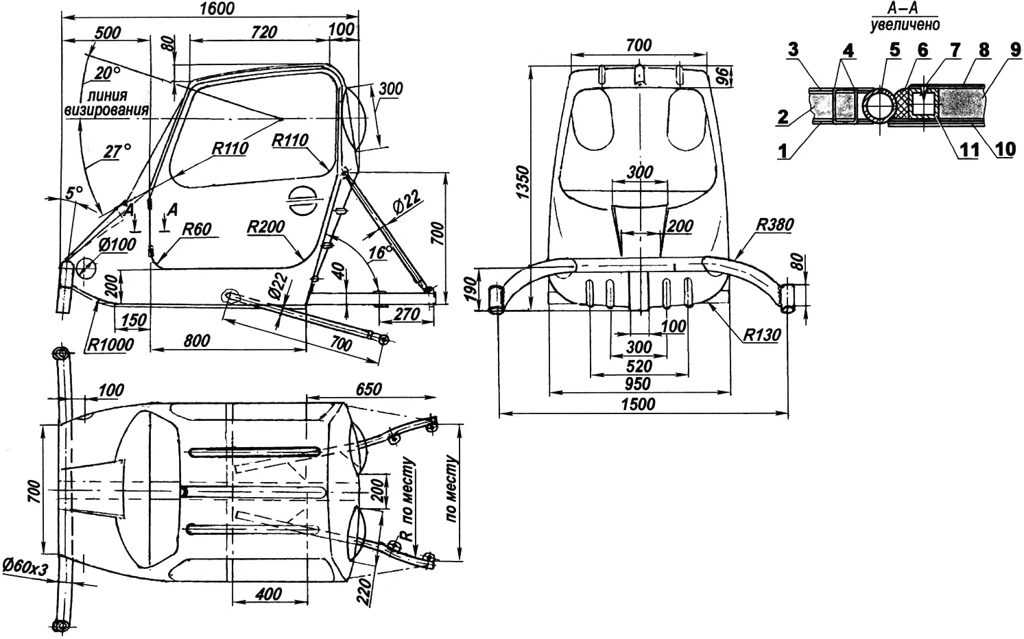
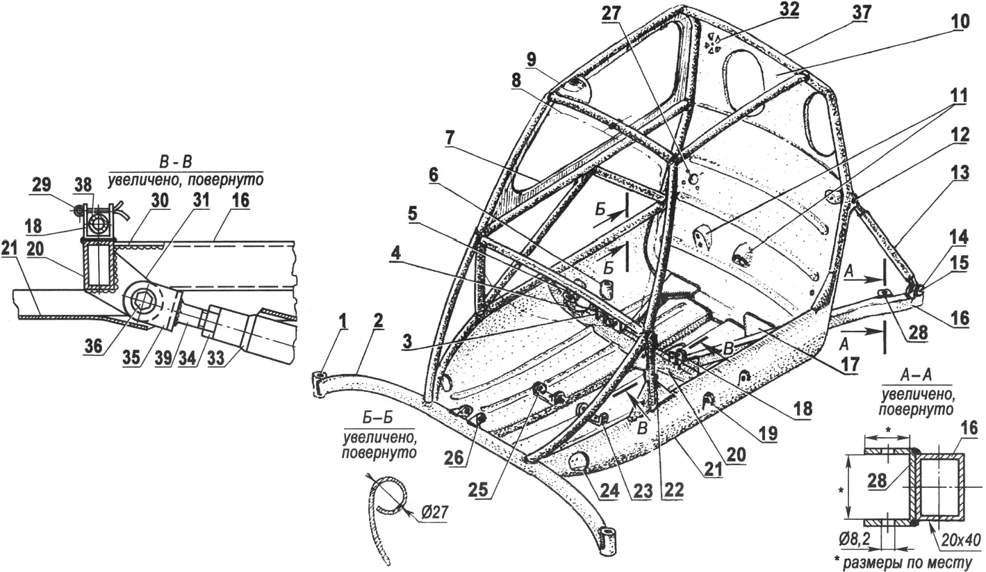
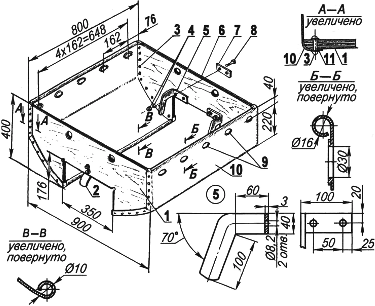
The cab is enclosed, single-seat, with one door on the left. The frame is mostly welded from thin-wall steel tubes of 27 mm OD; at critical joints gussets add strength. Only the crossbeam, which is both the front lower frame cross member and the bridge beam, is two-inch tube with 3 mm wall. Floor and rear wall are 1.8 mm steel sheet. Floor stiffness comes from a full-length channel, slight keel and “zigs” (ribs), and sides rolled into tubes. Carburetor and brake cables run in the channel. The channel also collects melt water, which drains aft through a hole in the floor rear. Dense felt is glued over the entire inner floor except the channel; the rear wall has the same insulation.
A simple subframe of rectangular tubes joins cab to snowmobile: two consoles tied at the front by a cross member. Consoles pass through the rear wall and are welded with gussets, and with the cross member to the floor. Gussets support the seat. At the rear, consoles bent to the Buran bumper profile carry fork-lugs with bolt holes; bolts pass through the bumper in field-drilled holes. Consoles are also braced to the cab, and the snowmobile is tied down with a tensioner.
1 — ski swing arm; 2 — gusset (steel sheet s3, 4 pcs.); 3 — bracket (steel sheet s5); 4 — axle; 5 — M12×1 nut (2 pcs.); 6 — silent block; 7 — spacer bushing; 8 — strut; 9 — swing lever
The subframe cross member carries seat-mount forks, the snowmobile reverse-reducer lever bracket, and an arched heater shelf. A lug welded under the centre ties with an adjustable strut to the snowmobile ski kingpin.
Sides, door, roof and cab nose are three-ply: outer and inner plywood with foam between. Skins attach to frame tubes with small countersunk screws; inner and outer panels are also stapled with wire staples. Epoxy ties it together: epoxy-based filler seals flaws after skin fit-up. The surface is sanded, covered with one layer of fine glass cloth, sanded again, then nitro enamel is sprayed — here bright red.
Forward is the service hatch cover, hinged to open ahead, held by a spring latch. Inside the cover is a pocket for an emergency kit.
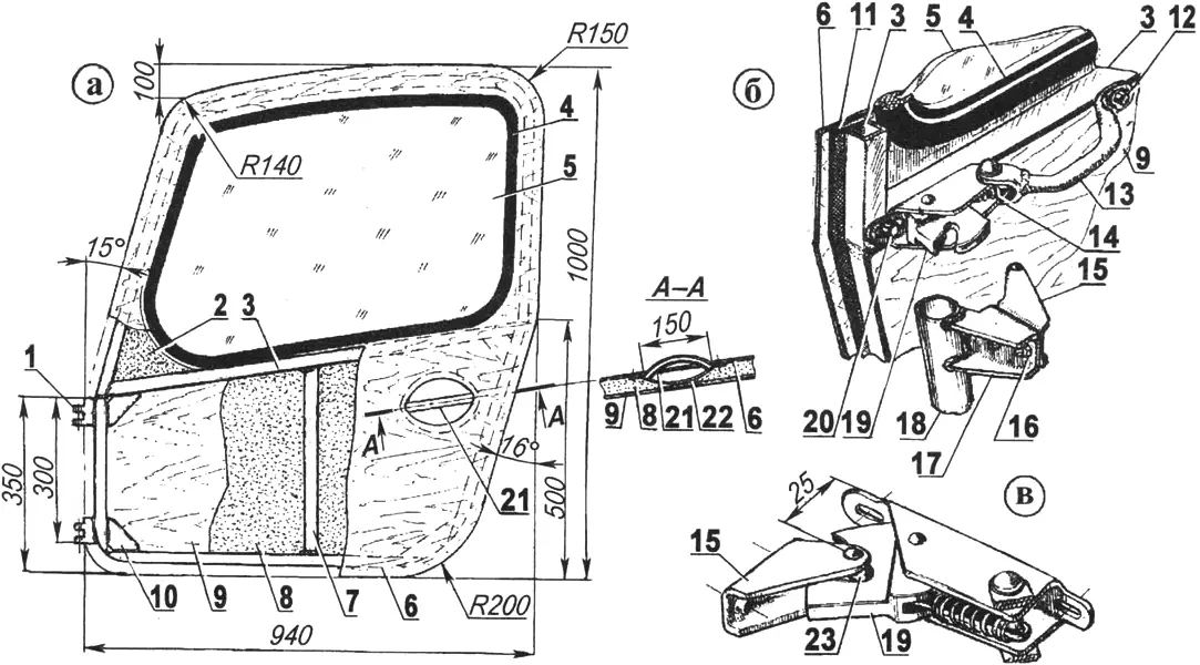
1 — hinge half (2 pcs.); 2, 8 — filler (foam); 3, 7 — door frame members (steel tube 20×20×1.5); 4 — windshield seal (rubber); 5 — windshield (s4); 6 — outer skin (plywood s5); 9 — inner skin (plywood s3); 10 — U-gusset (steel sheet s1.5, 3 pcs.); 11 — door seal (foam rubber); 12,20 — lock mount (M6 bolt); 13 — inner handle; 14 — normally expanded spring; 15 — catch bracket; 16 — welded M6 nut (2 pcs.); 17 — bracket; 18 — cab frame tube; 19 — pawl; 21 — outer handle; 22 — handle cup; 23 — catch
For ease of use the cab has a wide door. For the same reason the wheel is a sector (half-ring) with its hub moved 200 mm forward. The seat is raised (at some cost to the centre of gravity); it is from an S3D microcar, heavily modified but keeping adjustments. A headrest pad in the rear spherical view windows protects the head.
The windshield is acrylic. All glazing is framed with seals. A hand-operated wiper clears the windshield. For night running a roof lamp uses a ball mount and lock so it can serve as road light or searchlight.
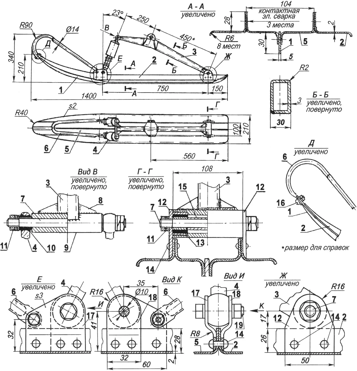
1 — wear strip (stainless steel sheet s5); 2 — left outer ski shell, right mirror (stainless s2, 2 pcs.); 3 — swing arm (steel sheet s3); 4 — shock absorber (from MMVZ motorcycle, 2 pcs.); 5 — left inner shell, right mirror (stainless s2, 2 pcs.); 6 — reinforcement (tube Ø14×2); 7 — swing arm axle (M12×1 stud, 2 pcs.); 8 — U-gusset (steel sheet s1.5, 4 pcs.); 9 — welded bushing (Ø20×Ø13×108, 2 pcs.); 10 — shock upper silent block; 11 — M12×1 nut with washers (6 sets); 12 — rear bracket (steel sheet s3, 2 pcs.); 13 — swing arm lower silent block (2 pcs.); 14 — rivet (steel Ø4, 12 pcs.); 15 — spacer bushing; 16 — reinforcement-to-ski mount (M6 bolt, 3 pcs.); 17 — front left outer bracket (steel s3, 2 pcs.; right outer mirror, 2 pcs.); 18 — front inner bracket (steel s3, 2 pcs.); 19 — shock lower mount to ski (M10 bolt, 2 pcs.)
The door frame is welded from square tubes. The lower door is three-layer; the upper section carries the windshield in its seal. The door hangs on two adjustable hinges; inner and outer handles and a latch are fitted. A cable stirrup-footboard aids entry.
Salon heat comes from a heater on the seat right, held by a special strap. Warm air is directed to the driver’s feet. The heater fuel tank is outside the cab on the left frame rail, clamped with a rubber pad. An electric fuel pump and sediment filter are tapped into the fuel line, which runs inside the cab.
1 — cab rear wall; 2 — throttle cable hole; 3 — stop; 4 — zig rib; 5 — brake cable (flex sheath); 6 — lightening hole; 7 — damper; 8 — cab floor; 9 — bracket; 10 — pedal (tube Ø10×2); 11 — rubber ring (3 pcs.); 12 — connecting rod; 13 — bracket (steel sheet s3); 14,16 — Belleville washer; 15 — normally expanded spring; 17 — clamp; 18 — link (steel rod 5); 19 — cable (Ø3); 20 — bracket; 21 — cable sheath stop; 22 — weld seam; 23 — brass bushing
Using a gasoline heater requires strict fire safety, careful handling, keeping the unit serviceable, and always carrying an extinguisher in the cab. Ventilation slots with shutters are on the upper right of the rear wall.
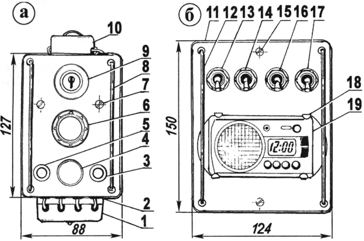
1 — fuse block; 2 — insulated feed-through bushing (rubber, 5 pcs.); 3 — heater indicator lamp; 4 — heater switch; 5 — generator run lamp; 6 — heater glow plug indicator; 7 — M5 panel screw, 2 pcs.; 8 — guard strap; 9 — ignition switch; 10 — 12 V socket for portable lamp; 11 — panel housing (steel sheet s1.5); 12 — guard strap; 13 — headlamp on toggle; 14 — headlamp high/low toggle; 15 — M5 switch-panel screw (2 pcs.); 16 — dome lamp toggle; 17 — spare toggle; 18 — radio spring clips (4 pcs.); 19 — dual-band AM/FM radio with clock
Electrical loads are controlled from lower and upper panels. The upper panel carries a removable AM/FM clock radio; in its dock it auto-connects to an external telescopic antenna. Nearby toggles run headlamp and dome circuits plus a spare for extra loads. The lower panel has a 12 V portable-lamp socket, ignition switch, heater glow indicator, generator lamp, heater switch, heater lamp, and fuse block.
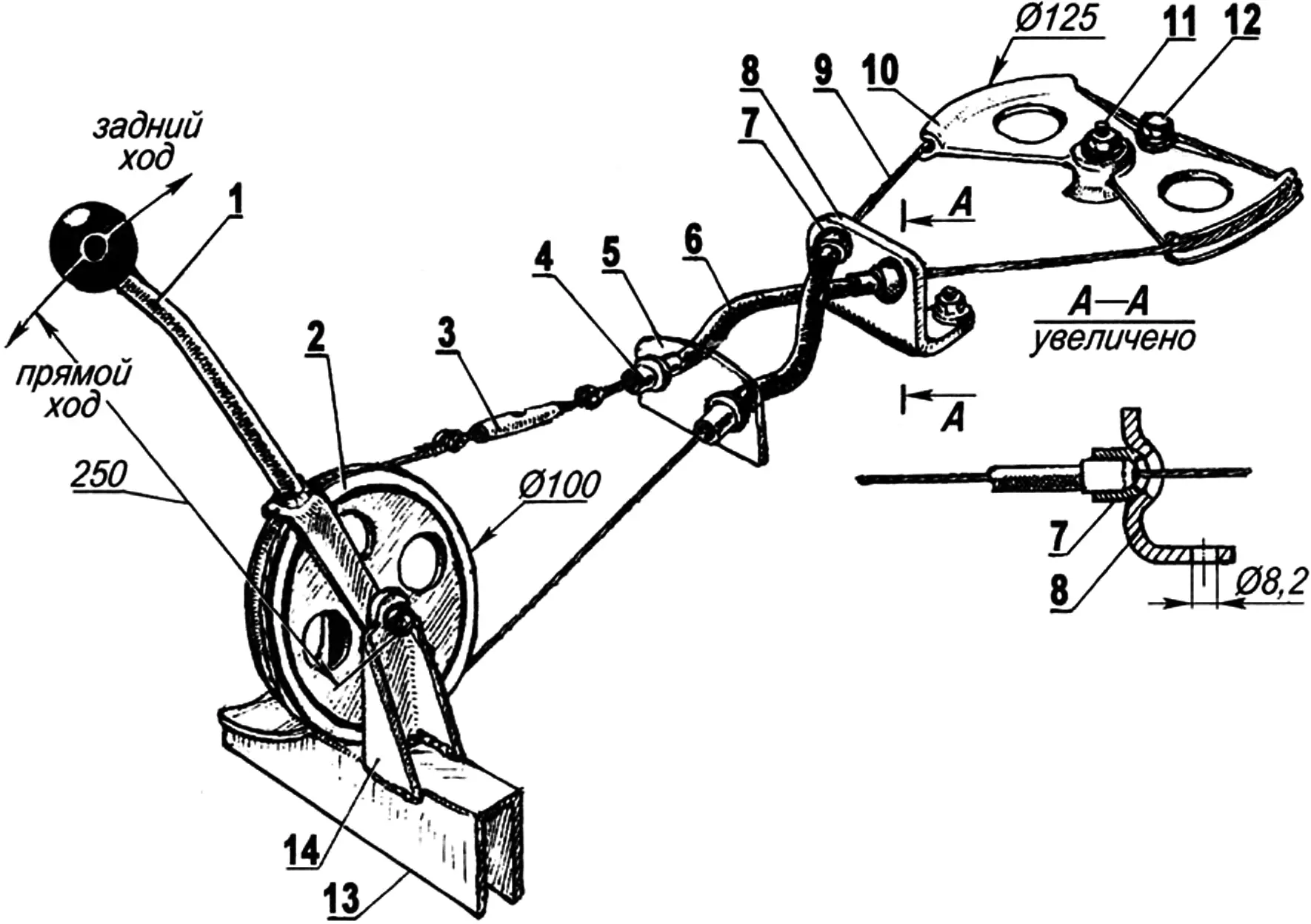
1 — lever; 2 — pulley; 3 — turnbuckle; 4 — stop; 5 — cab rear wall; 6 — cable flex conduit; 7 — ball thrust; 8 — bracket; 9 — cable; 10 — sector; 11 — reverse-reducer lever rod; 12 — lock bolt; 13 — subframe cross member; 14 — reverse shift lever mount bracket
Main interconnect wires run inside cab frame tubes; holes at penetrations use rubber bushings. 12 V power and snowmobile circuits arrive on a flexible multi-core cable with male/female connectors on the cab rear wall.
Steering gear and tie rods are from an S3D microcar, partly modified. The 400 mm wheel is homemade. An emergency engine stop button is in the wheel hub.
1 — front wall (plywood s12); 2 — front retainer (steel strip 30×4); 3 — rivet (aluminium Ø3 as needed); 4 — M8 nut with spring washer (4 sets); 5 — rear right retainer (steel sheet s3, left mirror); 6 — rear wall (plywood s12); 7 — strap (steel sheet s3); 8 — M8 bolt (4 pcs.); 9 — tie-down rope holes (14 pcs.); 10 — side panel (steel sheet s1.5, 2 pcs.); 11 — washer (as needed)
Skis are stainless steel: pre-bent panels spot-welded together.
In use, wide ski track and limited steer angle plus long wheelbase need plenty of room to manoeuvre. Heavy loads in the cab–snowmobile joint limit speed. Be especially careful on unknown routes where snow hides obstacles.
Extra cooling vs snowmobile speed
| Snowmobile speed plus wind speed, km/h | 8 | 16 | 24 | 32 | 40 | 48 | 56 | 64 | 72 | 80 |
|---|---|---|---|---|---|---|---|---|---|---|
| Ambient air temperature, °C | Effective temperature with extra cooling while moving, °C | |||||||||
| +2 | 0 | -6 | -9 | -12 | -14 | -15 | -16 | -17 | -17 | -18 |
| -1 | -3 | -9 | -13 | -16 | -18 | -19 | -20 | -21 | -22 | -23 |
| -4 | -6 | -12 | -16 | -19 | -22 | -23 | -24 | -26 | -26 | -27 |
| -7 | -9 | -16 | -21 | -23 | -26 | -28 | -29 | -29 | -30 | -31 |
| -10 | -12 | -19 | -24 | -27 | -30 | -32 | -33 | -34 | -35 | -35 |
| -12 | -14 | -23 | -28 | -32 | -34 | -36 | -37 | -38 | -39 | -40 |
| -15 | -18 | -26 | -33 | -36 | -38 | -40 | -41 | -43 | -44 | -45 |
| -18 | -21 | -29 | -38 | -40 | -42 | -44 | -46 | -47 | -48 | -49 |
| -21 | -23 | -33 | -40 | -43 | -46 | -48 | -50 | -52 | -53 | -53 |
| -24 | -26 | -36 | -43 | -47 | -51 | -53 | -55 | -56 | -57 | -58 |
| -26 | -29 | -40 | -47 | -51 | -55 | -57 | -59 | -61 | -62 | -62 |
| -29 | -32 | -43 | -50 | -55 | -58 | -61 | -63 | -65 | -66 | -67 |
Example: ambient air −10 °C, snowmobile speed (no wind) 40 km/h. Effective temperature with extra cooling −30 °C.
In closing, lack of space prevented fully implementing the plan. Often a compromise was needed (hence the tandem name), trading function for what was realistically buildable.
I hope readers who repeat my design will improve it greatly.
Brief technical data
Seats (including driver) … 3
Max useful cargo mass in bed, kg … 200
Overall dimensions, mm:
length … 4500
width … 1710
height … 1720
Cab ground clearance, mm … 300
Ski track, mm … 1500
Max speed at rated load, km/h … 45
Cab suspension … independent, spring-hydraulic
Cab heater (model) … 015V — 0010
Heat output (rated) … 1750 kcal/h
Fuel consumption (rated) … 0.35 L/h
«Modelist-Konstruktor» No. 1’2007, V. PETROV
Recommend to read
 THE FOG CREATES A SPEED
The boat standing at the dock, nothing attracted attention. Except that instead of a outboard motor on it was a propulsion system with a propeller of relatively small diameter at the... A ROCKET WITH A STREAMER
The design sports a model rocket with a streamer class Б6А traditional. Athletes rocketmodeler repeatedly noted that models in this class closer to a kind of optimum. Now much depends on...
