These days hobbyists are spoiled for choice: there is all manner of tools — it is hard to decide! Hand-powered and electric alike… I bought myself a handheld wood router (model IE-5003). Overall it is a decent machine: a wide range of operations, easy to handle, acceptable specs, spindle speeds up to 30,000 rpm, power — 500 W.
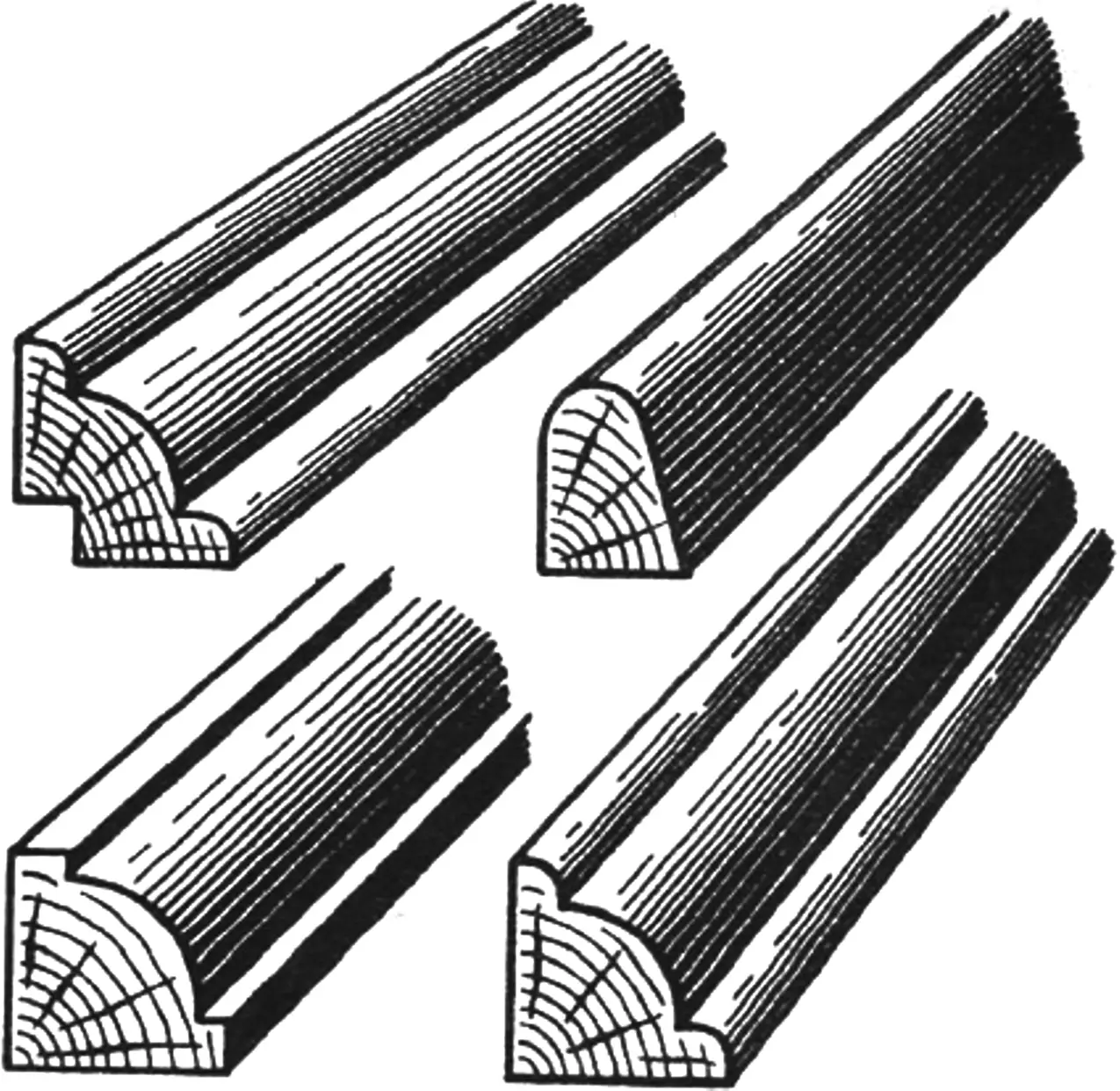
But it also has drawbacks. Two of them, in my view, are serious. First, the stock sub-base has a large central cutout (60 mm), which inevitably spoils the ends of the workpiece. Second, the blank must be rigidly clamped while feed is done by moving the machine. That workflow is very awkward for long, slender parts such as glazing beads, baseboards, and so on. Both quality and productivity suffer.
So the idea arose to turn the IE-5003 into a stationary wood-routing mini bench. What came of it is shown in the figure.
The machine base is the frame of an old aquarium, 600×300×300 mm, made of 25×25 mm steel angle. Almost any sheet stock will do for the table: steel, duralumin, plywood, textolite. I used 10 mm acrylic. Of what I had on hand it seemed the best fit: stiff enough, easy to machine on the bench or by hand, and bonds reliably.
A shaped opening for the bit and vacuum hose port is cut in the center of the table, copied from the router’s stock plate. Four bosses are glued to the underside; two round rods pass through them. The router is skewered on the rods like kebabs. The rods in the bosses and the machine on the rods are locked with knurled thumbscrews.
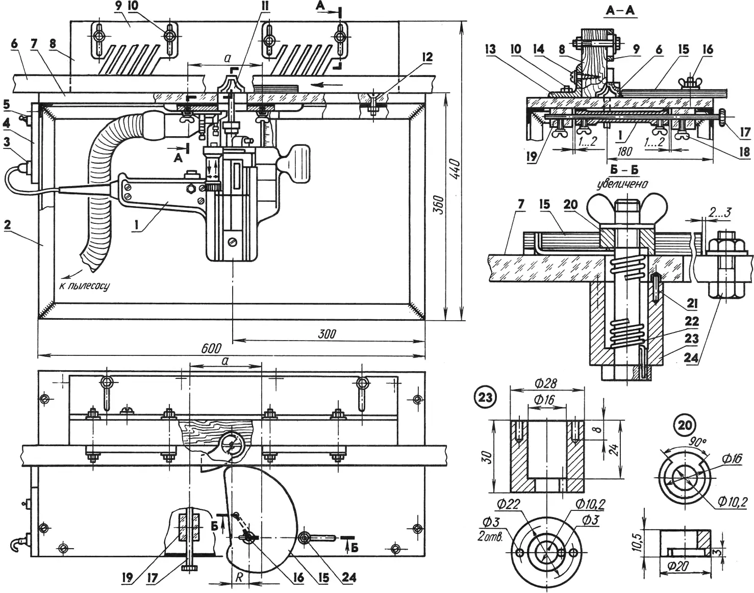
1 — handheld electric router (IE-5003), 2 — base frame (25×25 steel angle), 3 — 220 V socket, 4 — electrical panel plate (textolite s10 — 12), 5 — toggle switch, 6 — workpiece, 7 — table (acrylic s10 — 12), 8 — guide rail (pine, 40×80 bar), 9 — hold-down comb (plywood s10, 2 pcs.), 10 — M8 bolt, nut, washer (6 sets), 11 — router bit, 12 — M6 bolt (14 pcs.), 13 — guide bracket (50×50 duralumin angle, L540), 14 — 5×40 wood screw (2 pcs.), 15 — cam hold-down (plywood s10), 16 — M10 bolt, wing nut, washer, 17 — rod (steel bar, L300, 2 pcs.), 18 — M6 knurled thumb screw (8 pcs.), 19 — boss (acrylic, 4 pcs.), 20 — bushing, 21 — locking pin (steel bar, L10, 2 pcs.), 22 — torsion spring, 23 — sleeve, 24 — stop (M8 bolt, nut, washer).
To keep the required center distances, coaxiality of the guide holes, and 1—2 mm clearances (section A—A), the bosses were glued to the table already assembled with the rods and machine. That way perpendicularity of the bit to the table was ensured, which is critical for good results.
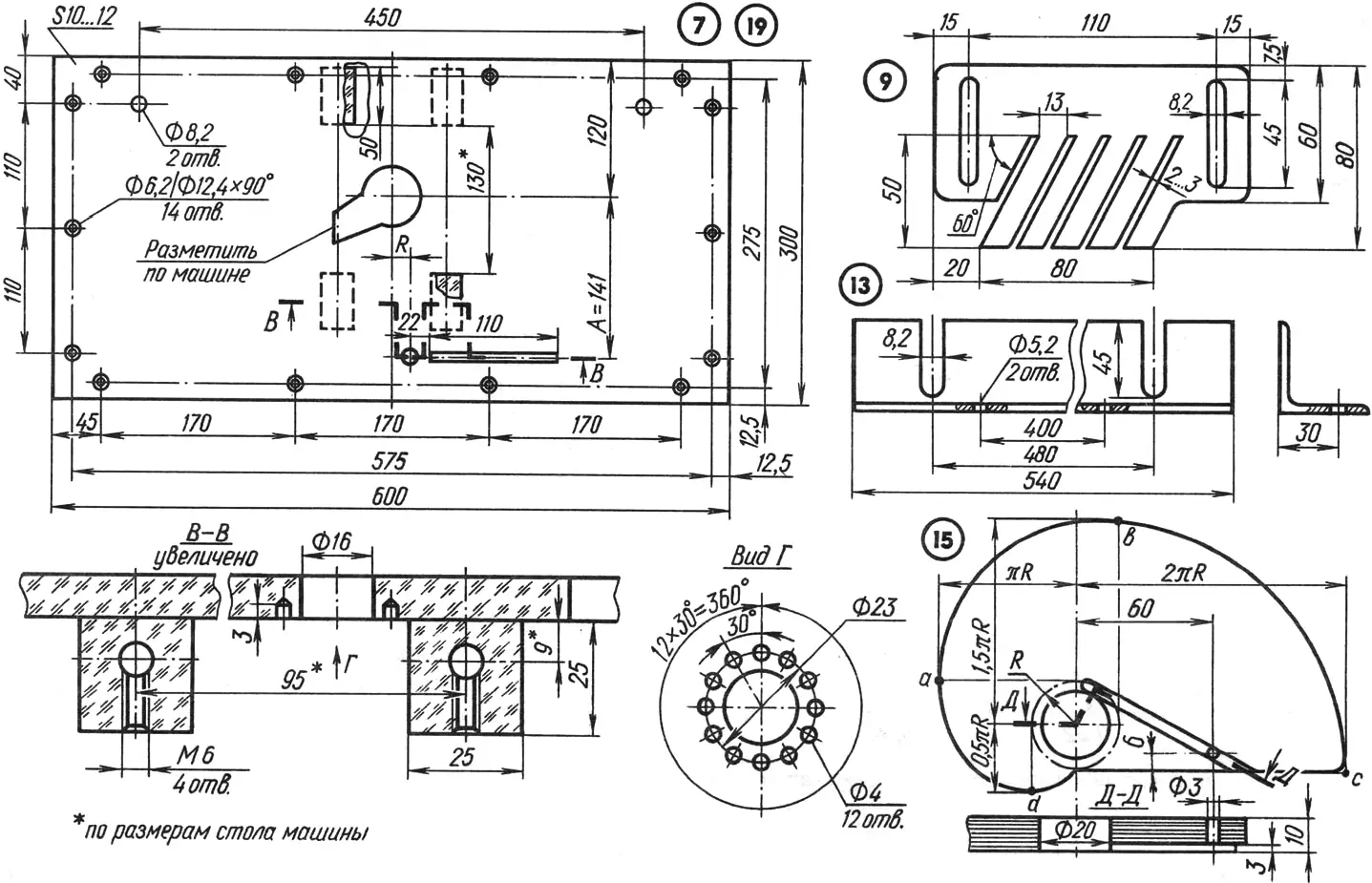
For straight work a guide is fitted: a bracket of duralumin angle (the larger the section, the better) with a removable wooden bar screwed on, chosen to suit the workpiece size. A recess is cut at the base center of the guide bar to clear the bit (when only the edges are machined), and four 8.2 mm holes are drilled through the top face to bolt on two wooden (or plywood) combs. They sit over the infeed (ahead of the bit) and outfeed. Spring action from angled slots gives the needed downforce on the table and helps prevent kickback. Vertical slots adjust clamping force with workpiece height. The comb faces are sanded.
The workpiece is pressed sideways to the guide by a spring-loaded cam whose working profile (c—d) is an involute of radius R. With the cam axis R to the right of the bit axis, the involute gives tangential clamping opposite the bit axis regardless of workpiece width.
Involute layout is covered in many drafting texts and manuals, illustrated in the figure, and needs no extra comment. We focus on finding radius R. The starting point is the width range b of the parts. Here: bmin ~ 10 mm, bmax ~ 110 mm. From the figure:
2πR-0,5πR = 110-10,
hence R = 21 mm, and distance A between the cam and bit axes
2πR + bmin ~ 141 mm.
The clamping force comes from a torsion spring wound on an 11 mm mandrel from 2 mm wire. The spring fits over an M10 bolt through the sleeve, table, and cam bushing (section B—B). The lower spring end passes into holes in the sleeve bottom and bolt head; the upper end follows a slot and a hole in the cam. Two 3 mm dowels are pressed into the top of the sleeve; they enter pockets drilled under the table around the 16 mm hole and prevent rotation.
To the right of the clamp, a stop fixed through a table slot keeps the clamp from unwinding after the cut.
To set clamp force: slide the stop right after loosening the nut. Back the wing nut a few turns, lower the sleeve until the locking pins clear the pockets. Place the workpiece against the guide, bring up the clamp, and rotate the sleeve, winding the spring to the desired torque. Engage the pins in the nearest pockets and tighten the wing nut. Bring the stop to 2—3 mm from the clamp and lock it.
All other router adjustments follow the supplied manual.
Modelist-Konstruktor No. 4’98, A. UZDIN
Recommend to read
 HANDLE COILS
Files generally are available without handles, and the latter may not be available at the time of purchase. To make them yourself is not everyone's strength. But this method is available... HUMBLE BUT STRONG
I love tinkering and doing this for a long time; in many ways helps your magazine. So I decided to share my humble experience. A few years ago, designed his own house table. I don't even...
