ONE WAY IS DIFFERENTIAL

SIDING INSTEAD

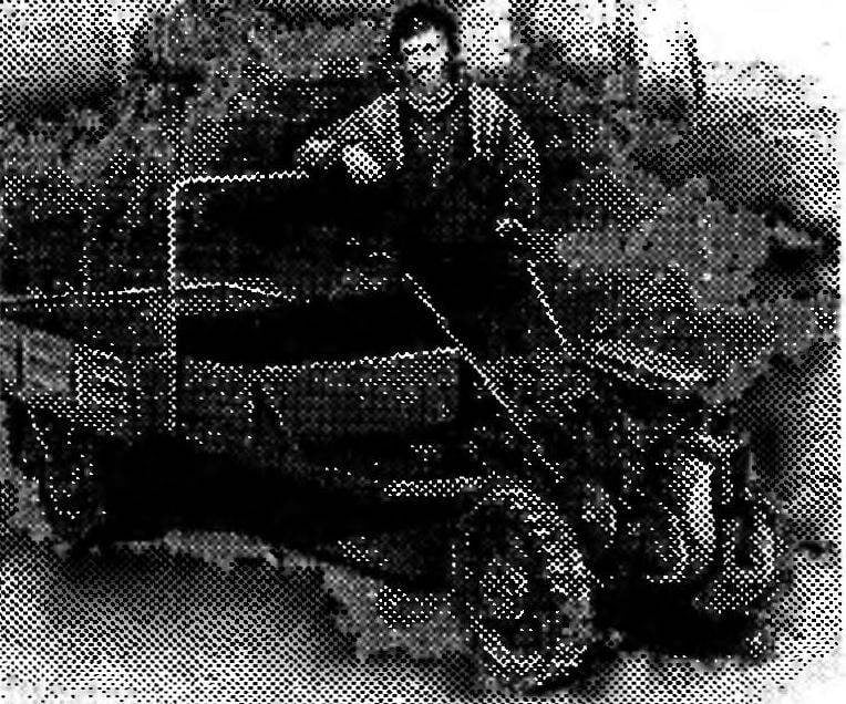
The need to have in personal possession a nimble and reliable metabolomic I (as probably many others in a similar situation) keenly felt, when he became the owner of a suburban area. On a mini-tractor of forces and means is not enough, therefore, decided to limit tillers, focusing on development that are found in binders “Modeller-designer”. The matter came creatively. As a result, fortune, which is published in the “Panorama” (“modelist-Konstruktor” No. 10 of 1984). Collected for the first own hands a cultivator followed by a second, third… And now the fifth, successfully proven in practice design (Fig. 1).
Tillers with maximum use made of industrial parts and components. In particular, sprocket and chain PR-15,875 — from discarded farming machinery. As, however, and overrunning clutch with rubber wheels. As a final good is a “suspension” of the rake GP-14. But it is possible to adapt and that offer through the trading network, the creators of the widely used industrial motor cultivator “Mole”.
 
“Energy heart” of the structure in question is the power unit T-200 (or similar, like on the scooter cargo “the Ant”), Intermediate, and output shafts of a two-stage chain transmission is installed in ball bearings 1680206С17 with tensioning sleeves (from straw walkers of the combine harvester “Niva”). Moreover, the housing of these bearings are attached to welded frame-muffler bolts M10, “zakonchennyi” nuts with washers.
 
Fuel to the engine flows by gravity from the bracket is installed on cosine (rear) and two 200-mm studs M8 (front) of the tank (taken from a motorbike). As shown by many years of operation, this solution is justified.
 
To the tillers while driving “behaved” quite stable, transmission of torque to the wheels usually tend to implement via the differential. However, I acted differently. Instead of the costly differential ventured to use a roller freewheel with charged grain drill. In the presence of certain tokarno-mechanical skills you can do it yourself. The more that each one has only three (Fig. 5) basic, not so difficult to produce item: ferrule, hub and operating as a unit triad movies.
 
During the rotation of the hub in a clockwise direction the rollers are automatically rolled in the tapered cavity and zakleivayut. The result is a clutch coupling for transmission of torque in the desired direction. If led detail overtakes the lead, the rollers roll out of the cavities, raceplay “kinematics”.
Had a good performance and another variant of the tillers using a homemade ratchet overrunning clutches. Hub for her is made from structural steel and installed on the output shaft with bronze bushings, pressed on with an interference fit, and then saccomanni. Grease provides pressure lubricator.
 
From the axial displacement of the hub to limit one side of the retaining ring, on the other — the body of the freewheel. Between them to reduce friction losses, there is a bronze thrust washer with a thickness of 2,0 mm.
 
For mounting the drive road wheels to the hub welded flange (counting the four holes on the disk). On the other end of the hub is pressed onto the ratchet, which is held from turning prismatic key. It is made of carbon steel plate 20 mm thick, has 12 teeth with a height of 7 mm, fits into a circle with a diameter of 74 mm.
 
The housing freewheel is fixed on the output shaft of the three lock screws located in the same plane at an angle of 120″ to each other, which made corresponding indentations. The driven sprocket is attached to drive the five M8 bolts (marking holes on the drive — sprocket holes). The axis of the pawl (Fig. 6) pressed against the ratchet by a spring.
 
The EPS control unit is sliding, is made of two pairs of cold-rolled seamless steel pipes entering each other. Installed it on the frame with hinged joints for rotation in the vertical plane of tillers at 80°. This gives the possibility to treat the soil directly under the canopy of shrubs and fruit trees. On the right arm placed lever “gas”, which regulate the throttle position. The left arm is a lever “grip”.
 
Fig.1. Tillers (lining removed), packaged truck (a) and cultivators (b)
 
 
Fig.1. Tillers (lining removed), packaged truck (a) and cultivators (b):
1 —frame-muffler, 2— lever, kick starter, 3 — power unit, 4 — node, intermediate shaft, 5 — star, first-stage chain transmission, 6 — tank,7 — block steering, 8 — shift lever, 9 — right arm with lever “gas”, 10 — left arm to the lever “the clutch”, 11 — seat 12—a tool box. 1 3 — “front” cargo truck, 14 — foot brake-trailer 15 — driving wheel (2 PCs.), 16 — overrunning clutch (2 PCs), 17 — sprocket of the second stage chain transmission, 18 — hoe cultivator (2), 19 — front cultivator (2 PCs), 20 — D-shaped frame sides.


Fig.2. Kinematic scheme of transmission
 
 
Fig.2. Kinematic scheme of transmission:
1 — power unit T-200, 2 — chain drive, 3 — intermediate shaft 4 — self-aligning bearing I 1680206С17 (4 PCs), 5 — output shaft 6 — way wheel (2 piece), 7 — roller overrunning clutch (2); and — the option of the ratchet one-way clutch.


Fig.3. Frame-muffler (welded construction)
 
 
Fig.3. Frame-muffler (welded construction):
1 — nozzle inlet (the stainless steel pipe 50x 1,5 L30), 2 – bracket vertical (St3, strip s5). 3 — pipe output (the stainless steel pipe 20×1,5 L30), 4 — “ear” (St3, strip of 6 pieces), 5 — bracket inclined (St3, sheet s5), 6 — sealing septum (St3, sheet s1,5), 7 — side panel of the docking station (STZ, the sheet s5, 2 PCs.), 8 — cross member (STZ, channel 100×46 L60), 9 — bracket output shaft (STZ, the sheet s7), 10 — cover, muffler (STZ, sheet s1,5), 11 — beam spinal (steel channel 160×64 L600).


Fig.4. Mount intermediate shaft
 
Fig.4. Mount the intermediate shaft:
1 —beam spinal, 2 — 1680206С17 self-aligning bearing (2 pieces) 3 — intermediate shaft 4 — bolt M10 with lock nut (4 PCs.).


Fig.5. Overrunning roller clutch
 
Fig.5. Overrunning roller clutch:
1 — clip (20X steel, HRC 56…62), 2 — hub (20KH steel, HRC 56…62), 3 —roller (steel SHKH15, HRC 30…40, 3 pieces), 4 — cheek (45 steel, sheet s2,5, HRC 30…40, 2 PCs.), 5 — dowel prismatic (steel 20KHN), 6 — washer-lock split (2 piece), 7 — spring (steel wire diameter 0.5 3 PCs.).
 

Fig.6. Node one-way ratchet clutch Assembly with the sprocket of the chain transmission on the output shaft
 
Fig.6. Node one-way ratchet clutch Assembly with the sprocket of the chain transmission on the output shaft:
1 — sprocket (steel 20KHN, z=45 and t= 15,875), 2 —enclosure (ft3), 3 — screw M12 flush with lock nut (3 PCs.), 4 — disk (steel 20), 5 — axle dog (steel 40KHN), 6 — washer, 7 — pin, 8 — dog (steel 20KHN), 9 — ratchet (steel 20KHN), 10 — bushing (Бр05Ц5С5, 2 PCs.), 11 — pressure lubricator, 12 — thrust washer (Brabbs, 2), 13 — screw, M10 flush with lock nut (2 PCs), 14 — retaining ring (STZ), 15 — flange (STZ), 16 — wheel hub (steel 45), 17 — a casing (STZ), 18 — bolt M8 with race-Cernunnos nut (5 PCs.), 19 — spring (steel wire, 0 to 0.8), 20 — key 4x4x18 prismatic (steel 45), 21 — output shaft (steel 45).


Fig.7. The EPS control unit (the shift lever is not shown)
 
Fig.7. The EPS control unit (the shift lever is not shown):
1 — main rod (steel tube 30×2,2, 2), 2 — “ear” (STZ, the sheet s5, 2 pieces) 3 — sleeve (steel tube 34×2, 2 PCs.), 4 — rod adjustment (steel pipe 25×2,2, 2), 5 — left arm (with the lever “grip” of the scooter), 6 — arm, right (with the lever “gas” of the scooter), 7 — a-line perforated (STZ, sheet s), 8 nut weld M8 (2 PCs), 9 — nut M8 (2 PCs), 10 — bolt locking M8 (2 PCs.)


technical data motoblock
 
The gear lever is on the right side. Moving forward include working speed and traveling itself — transport.
 
As already mentioned, the walk-behind used powerplant T-200 capacity 14 HP with forced air cooling. On the frame it is mounted using the vertical and inclined arms of steel strip with a thickness of 5 mm and three pairs of “ears”, the holes running in place during Assembly. Of chains PR-15,875 in a two-step transfer is performed by moving the intermediate shaft in the grooves of the sill. Output shaft, and intermediate, also rotates in bearings 1680206С17 only are they bottom of the frame and fasten using conventional bolted connections.
 
The entire drive system is arranged so that the center of gravity of the machine in longitudinal and transverse directions in the maximum extent provided the equilibrium of the structure. For this rather small pressure of the operator to handle steering.
 
Besides, it was possible to avoid additional stress on the front part of the bearing beams of the trailer while using tillers as vehicles, fully consistent with the idea underlying the whole construction. After all, the thought of the machine as a kind of mini-tractor for the work associated primarily with the movement of goods: with advanced truck from “Ant”, with a convenient (Keyway) seat (tool box) with reliable rotary drawbar and increased almost up to one ton carrying capacity.
 
The cultivator has fully justified these hopes.
 
As for the tillers, their linkage is carried out using a D-shaped beam (see Fig. 1), installed in the coupler box type with rigid fixation with two fingers with a diameter of 20 mm.
 
S. SHIRYAEV, city of Bekabad, Tashkent region.

Recommend to read

  • “KLINTSY” — UNIVERSAL MECHANICAL PATTERN“KLINTSY” — UNIVERSAL MECHANICAL PATTERN
    To check the symmetry of the punch of a model of the ship on the drawing manufactures all of its frames (or polosamote). Although this work is easy, but requires time and material cost....
  • NEW ROLE KEYNEW ROLE KEY
    If you think about it, the usual Bicycle pump extremely uncomfortable: after all, he had no supporting devices, such as, for example, a car. However, support cyclists... carry with them....