As a result, “growth” of tillers decreased by 350 mm. lowering the center of gravity in combination with increased to 500-700 mm wheel track (depending on pivot disks) gave the structure the necessary stability.
The doubt was caused and the long curved pipe to the carb — short, regular better. So I went back to him. To operate the engine more reliable, used electronic control unit and the ignition coil, and instead of the kick starter set the starter pulley on the fan shaft.
The scheme of the transmission, it was decided not to change. However, the intermediate and suspension bridges made themselves. For simplicity used splines of the sprocket shafts and keyways. And again. So it was easy to choose the optimal gear ratio, sprockets manufactured separately from the hub by affixing bolts.
Top chain for security are covered.
Somewhat dierent is we have a holder of the working body with handles of control: they can be fixed in any of the three provisions.
R and S. 4. Suspension shaft.
Fig. 5. Wheel hub bearing and starter pulley.
Fig. 6. Holder with knobs:
1 — frame 2 — loop suspension holder. 3 — bolt suspension holder, 4 — Bush. 5 — handle, 6 — leash clamp 7 — clamp, 8 — fee retainer. 9 — pin, 10 — tine carrier 11 is curved grip of the working body 12 — bolt suspension of the working body 13 — adjusting bolt 14 — axis of the adjusting bolt 15 — the end wall.
Fig. 7. A typical connection of the sprocket with the hub.
As plow our — paw cultivator bent back grip, that the land is not filled up right wheel.
Were critical we and the throttle lever, believing that to control the motor of the motor-block it is not suitable “lever” is better.
Now about the wheels. Support decided not to use and opted for two wheels from the sidecar С3А. Lugs placed on them at an angle of 45°, the “Christmas tree” that they were able to clean itself when plowing. Instead of chains put the wheels of steel tapes…
Your walk-behind guys named “Vyatka-1M”. The efforts spent by them on improving the design of “Vyatichi”, the gift is not lost, the machine works reliably. For the second season, they plow heavy loam. And quite quickly — three hundred parts per hour to a depth of 220 mm.
The intermediate shaft also serves as a walking tractor PTO. Connecting it to the pump, a circular saw or a mower, you can perform a number of additional chores.
Recommend to read
 COMFORT UNDER THE FILM
I am an old gardener, many years of perfecting his greenhouse. First staged in her warm bed: dug two-foot holes in the ground, put in it a layer of twigs, stems, and covered with...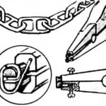 CHAIN — NOSE PLIERS
Respond to readers, share advice. When producing model ships can not do without the device for links of the anchor chains with buttresses. Minor refinement of pliers (or pliers)...

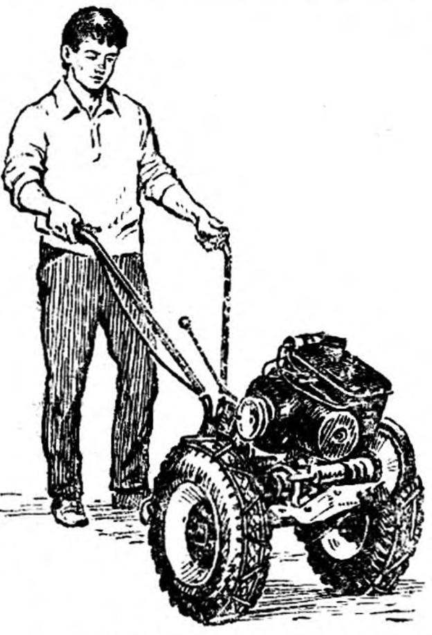 Which exhibit the most interesting? Obviously, the one with the most visitors, which often induce camera lenses. This exhibit at the Moscow city exhibition scientifically-technical creativity of youth in 1984, dedicated to the 60th anniversary of the Komsomol assignment of a name of V. I. Lenin, was the tillers “Vyatka-1M”, made in a circle autocostruzione of the Palace of pioneers and pupils named after N. K. Krupskaya of the Bauman district of Moscow!