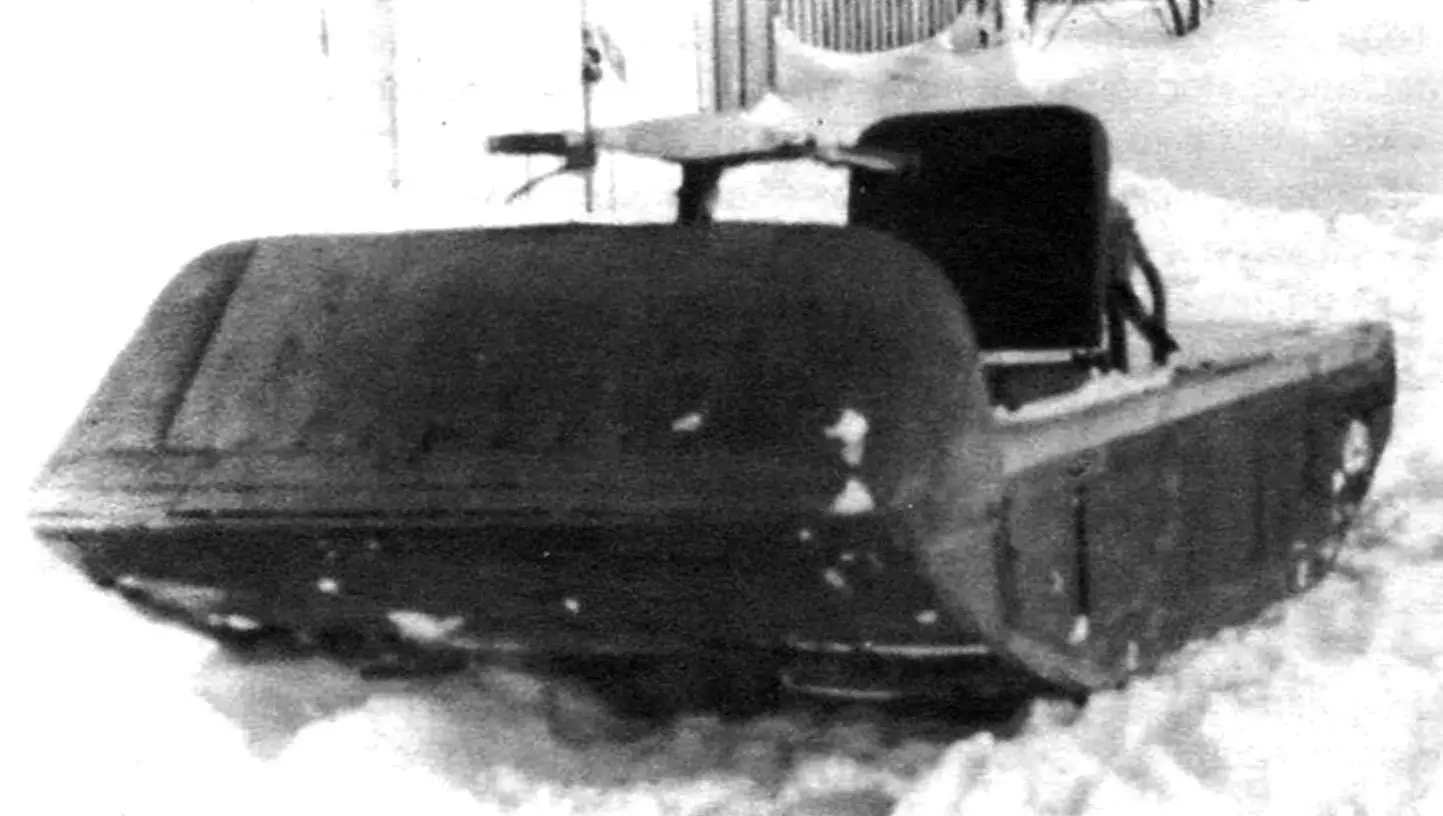
I was born and raised in a region where the ground stays under a thick snow cover for most of the year — so it’s no surprise that people consider this place the homeland of Ded Moroz. Probably, that’s why, alongside my general interest in technology, snowmobile machines have always drawn my special attention. Owning one was my cherished childhood dream. When I grew up and learned to do many things with my own hands, I decided to build my own design. By that time, I not only studied the construction of snowmobiles, but was also able to critically assess the advantages and disadvantages of such machines.
Surprisingly enough, even serial tracked snowmobiles, including imported and modern ones, are poorly suited for riding through deep, loose snow. While driving in such conditions, when you lean or turn, the rear part of the machine often sinks. Trying to get out by increasing engine RPM usually ends up with the track lugs digging into the snow even deeper. After that, getting the machine out of this snowy trap without outside help becomes difficult. And that makes sense: just consider its own weight — the “horse” is almost entirely steel. So after snowfalls and snowstorms, it’s better not to venture alone into forests and gullies on serial snowmobiles.
I built my own machine with those difficult conditions in mind, so it could be used even there.
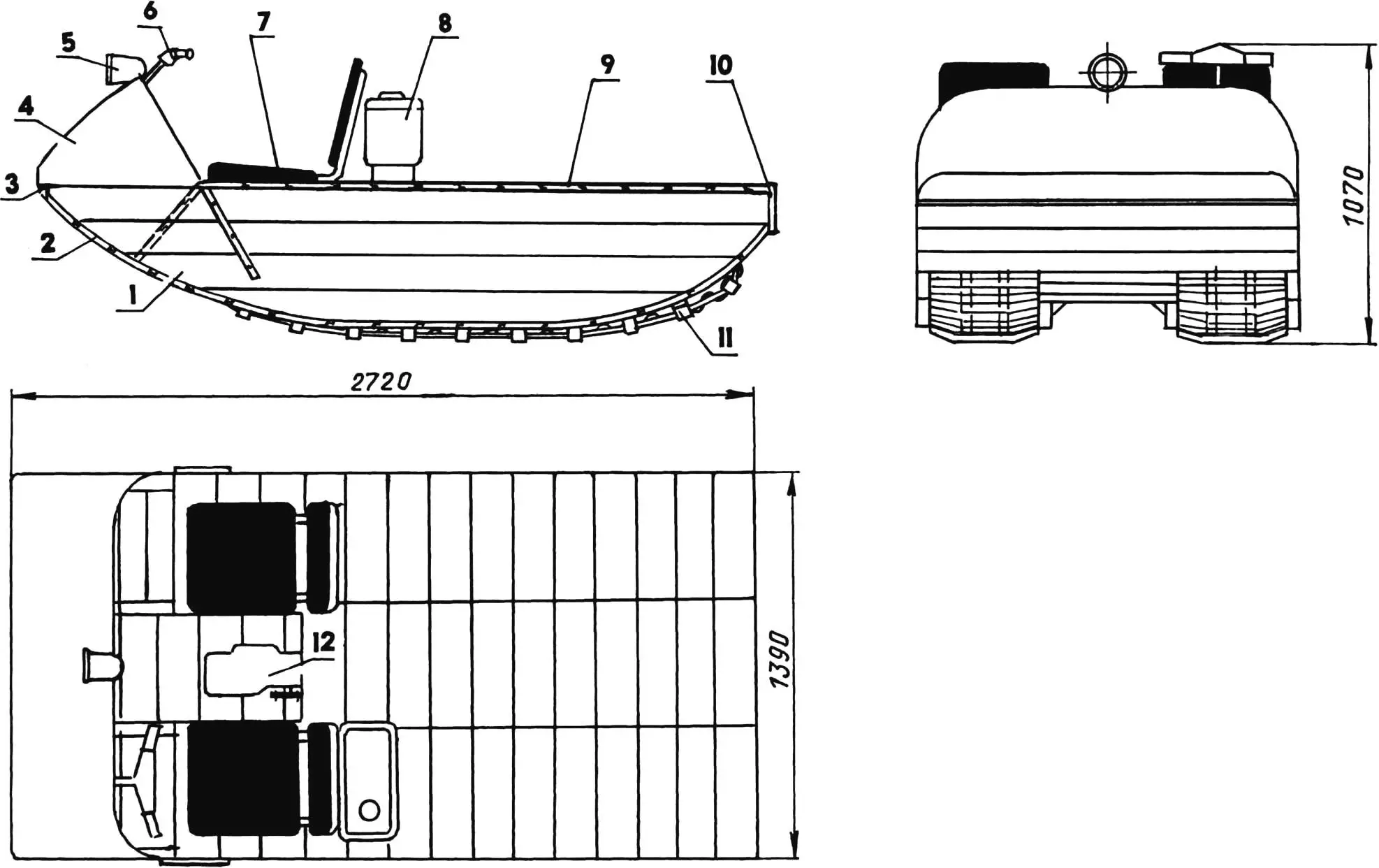
1 — side wall (boards s45, 4 pcs.); 2 — bottom lining (clapboard board s16); 3 — front bumper (board s45); 4 — hood (plywood s3); 5 — headlight (from a tractor); 6 — steering wheel (from the Vyatka-Electron moped); 7 — seat (from a LuAZ car, 2 pcs.); 8 — fuel tank; 9 — deck (clapboard board s16); 10 — rear bumper (board s45); 11 — track; 12 — engine
I made the snowmobile body wooden. I simply knocked it together from lumber, like a boat. The body is based on four longitudinal side walls made of coniferous wood (spruce, pine). I assembled the side walls from planed boards—“fifty-millimeters” (45 mm thick). Actually, they were more like beams, since their width was only slightly more than twice the thickness. I fastened the beams together with nails—“two-hundreds” along the edges, nailing each next beam to the previous one. I shifted the nails slightly along (forward or backward) so the upper one wouldn’t accidentally end up in the lower one’s head. I trimmed the ends of the beams with the marked guiding curves. The curve’s steepness in the front is smaller than in the rear.
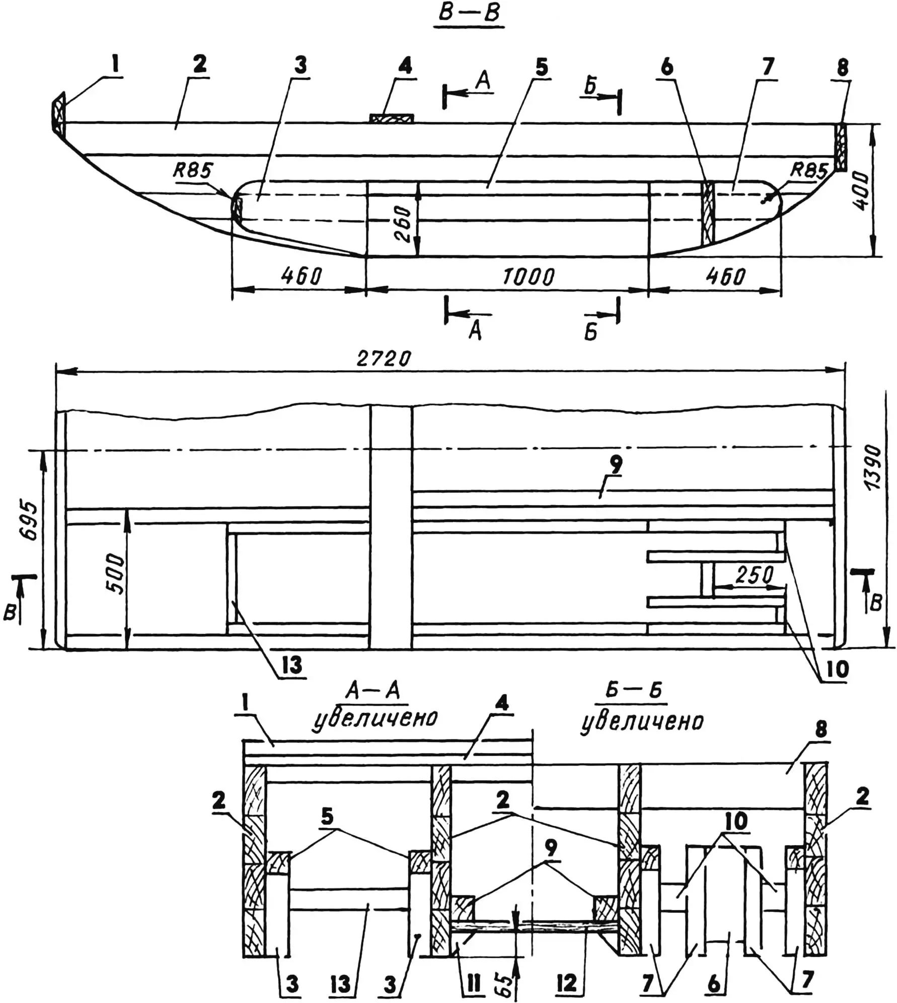
1 — front bumper (board s45); 2 — side walls (board s45, 4 pcs.); 3 — front rounded sections of the track box (board s45, 4 pcs.) 4 — cross member; 5 — ledger block of the track-box frame (45×45 timber, 4 pcs.); 6 — cross member of the rear roundings (board s45, 2 pcs.); 7 — rear roundings of the track box (board s45, 8 pcs.); 8 — rear bumper (board s45); 9 — mounting timbers of the transmission units (45×45 timber, 2 pcs.); 10 — technological cross members of the rear roundings (board s20, 4 pcs.); 11 — deck stop (45×45 timber, cut lengthwise along the diagonal); 12 — deck (clapboard board s16); 13 — technological cross member of the front roundings (board s20, 2 pcs.)
All four side walls are the same and connected to each other at the ends by the bumpers, and in the middle at the top by a cross member across the entire body width. I made the bumpers from planed “fifty” boards, and the cross member from “twenties”. But that’s not all. In many places, the side walls are connected pairwise with cladding boards: the outer ones with the nearest inner ones, and the inner ones with each other. In addition, to the side walls from the inside, I nailed timber members (as builders call them, “skull” blocks), and to them I also sewed boards (16 mm-thick clapboard) for cladding the track box sides (between the outer and middle side walls) and the bottom (between the middle walls). This entire transverse assembly gives the body enough rigidity without braces and tie rods. If additional fastening elements are needed, they can be installed where there are no moving mechanisms: inside the track-boxes and at the front and rear ends of the machine. Also, to the body I include those elements (side walls, partitions) that cover the track drive sprockets—so in those places snow does not get into the track boxes.
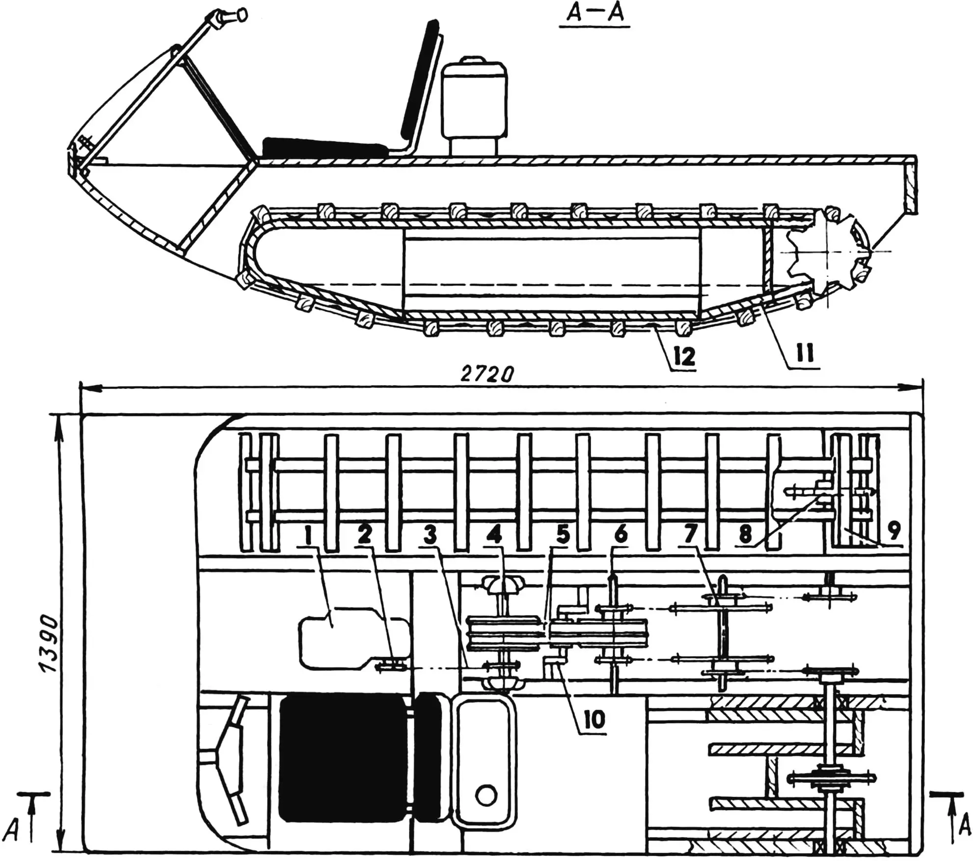
1 — power unit; 2 — sprocket of the output shaft of the power unit (z = 20, t = 19.05); 3 — chain between transmission units (single-row, t = 19.05, 5 pcs.); 4 — unit of the variator primary shaft; 5 — variator V-belts (type G, 2 pcs.); 6 — unit of the variator secondary shaft; 7 — unit of the intermediate shaft; 8 — unit of the track drive shaft; 9 — track; 10 — tensioning mechanism for the variator V-belts; 11 — lower additional lining of the track box (polyethylene, sheet s5); 12 — overlay (nylon, 20 pcs.)
The vertical sides of the track boxes are rounded, and the lower edges are chamfered so that the tracks can more easily climb small obstacles encountered along the way. At the bottom, the track boxes are additionally sheathed with a 5 mm sheet of polyethylene. The sheets are attached to the bottom with countersunk screws.
At the front of the body, the cladding is made as a floor in a recess for the driver’s and passenger’s feet. Above the recess, a steel angle arch 25×25 is installed. In the lower part, the angle is straightened into a strip, and this strip is fastened with screws on the outside to the extreme side walls. To the arch, using M4 bolts, and to the bumper—using nails—there is a plywood fairing attached.
The snowmobile equipment can hardly be called even Spartan: there are two seats on the sides—for the driver and passenger from a LuAZ car—and a moped steering wheel with controls, plus a headlight, because winter days are short.
The track propulsion system in my machine is very simple. It has no support rollers, idlers, and the like characteristic for this mechanism; there isn’t even a driven sprocket.
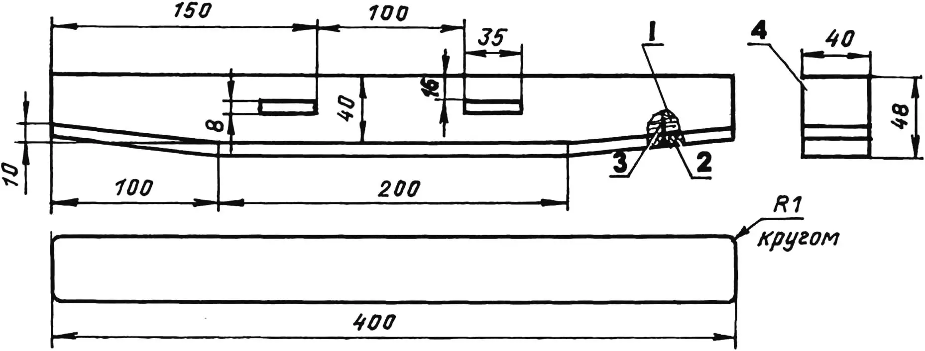
1 — bar (birch timber 40×40); 2 — sole (rubber from a V-belt s8); 3 — nail L30 (8 pcs.); 4 — insulation (fiberglass fabric on epoxy resin)
Making the track is not difficult. The lugs (track lugs) are made of birch blocks 40×40 mm. To prevent soaking and increase wear resistance, they are covered with fabric on epoxy resin. To the lower supporting surface of the lugs, soles are nailed—cut sections of a V-belt (or you can use a conveyor belt). The lugs are joined into a track using two long narrow belts with a cross-section of 35×8 mm cut from a conveyor belt. The belts are threaded through corresponding grooves in the lugs. The lugs are distributed along the length of the belts evenly, with an interval of 216 mm, equal to two tooth pitches of the drive sprocket, and nailed in place.
Looking ahead, I’ll say this: operation showed that when the track runs over the rounded part of the front track box, the belts catch and rub the cladding. So I had to nail, between the lugs on the inner sides of the belts, a pair of nails with hidden heads and nylon pads made in the form of segments. The nails are thin but long: their ends that came out on the outer side of the belt were bent with a bracket and driven back into the belt.
The finished track, though still separated, is put onto the box; the belt ends at the joint are trimmed into a long tab and connected with nails driven through a bracket. To avoid complicating the design, I didn’t make a track tensioning mechanism, leaving that “for later”, but during operation it never turned out to be needed.
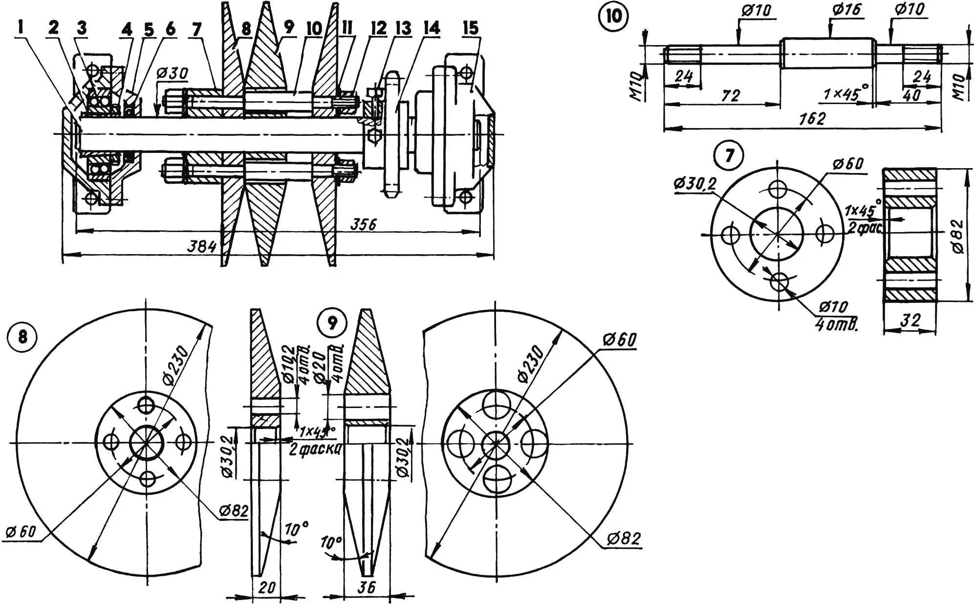
1 — blind cover of the bearing housing; 2 — bearing 11206 (2 pcs.); 3 — tapered bushing (2 pcs.); 4 — seal (3 pcs.); 5 — cheek of the track sprocket (steel, circle 100, 2 pcs.); 6 — drive sprocket of the track (nylon, sheet s20); 7 — M8 locking screw (6 pcs.); 8 — shaft (steel, circle 30); 9 — bearing housing (2 pcs.); 10 — M18x0.75 tightening nut (2 pcs.); 11 — cover with an opening for the bearing housing; 12 — leading sprocket of the shaft (z6 = 24, t = 19.05)
The track is driven by the drive sprocket. The sprocket has 7 teeth, and the number of lugs on the track is 21. The lug pitch is such that they engage every other tooth: that is, with each revolution of the sprocket, either one set of teeth or the neighboring one comes into work. This design of the sprocket significantly increases its service life, and also leaves the possibility to double the number of lugs on the track.
The power unit (engine with the gearbox) is from the Vyatka-Electron moped. It has its own forced air-cooling system. Therefore, I installed it in the central compartment of the body between the seats, behind the front cladding. On the snowmobile, it was used without modifications. I only lengthened the kickstarter lever and changed its position.
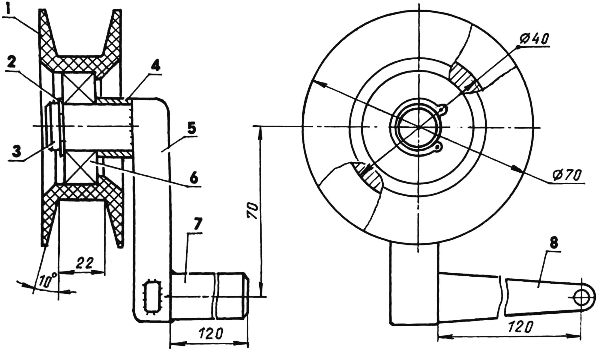
1 — roller (nylon); 2 — locking washer; 3 — roller axle; 4 — spacer bushing (steel, pipe 25×2.5); 5 — connecting rod; 6 — bearing 204; 7 — lever axle; 8 — lever (from agricultural equipment)
The snowmobile’s transmission, although simple, is not quite ordinary, and may even be original. Besides transmitting power and changing the torque, it also simultaneously serves for turning the machine while driving. But about that a bit later, when we talk about steering.
Torque from the output shaft of the power unit through a chain drive with a transmission ratio i1 = 0.8 is transmitted to the variator primary shaft with sliding pulleys, and then further to the fixed (non-sliding) pulleys of the secondary shaft using V-belts. Also, on the secondary shaft on different sides of the pulleys, two drive sprockets of the second-stage (reduction) chain drive are fixed—up to the intermediate shaft (transmission ratio i2 = 3.125). Another reduction chain drive of the third stage (transmission ratio i3 = 1.5) transmits torque to the track drive shaft with the sprocket. As a result, the overall transmission ratio of all chain drives is 3.75. The specified number of teeth on the sprockets is not that important—whoever chooses what, as long as the overall transmission ratio is maintained (at least approximately). I consider this to be optimal for this kind of machine: it doesn’t need high speed, 15–20 km is enough, and the pulling power is such that it can haul a significant load—at the same time, up to a dozen kids could ride on the snowmobile.
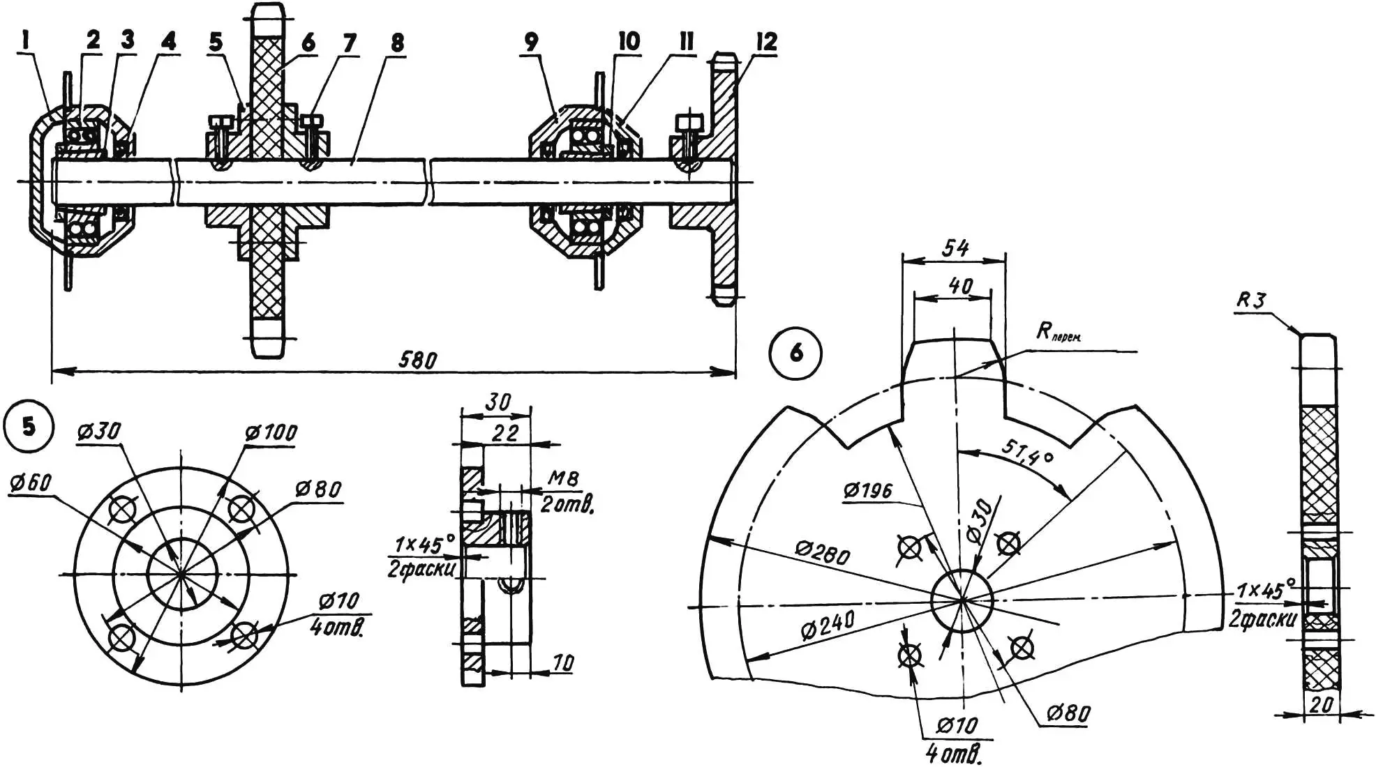
1 — shaft (steel); 2 — tapered bushing (2 pcs.); 3 — bearing 11206 (2 pcs.); 4 — M18x0.75 locking nut (2 pcs.); 5 — bearing housing cover (2 pcs.); 6 — seal (2 pcs.); 7 — flange bushing (steel, circle 82); 8 — fixed cheek of the variator pulley (steel, circle 230, 2 pcs.); 9 — movable cheek of the variator pulley (steel, circle 230); 10 — M10 stud (steel, circle 16, 2 pcs.); 11 — spring washer (8 pcs.); 12 — M10 nut (8 pcs.); 13 — M8 locking screw (2 pcs.); 14 — chain sprocket z2=l 6, t = 19.05; 15 — bearing housing with mounting platform (2 pcs.)
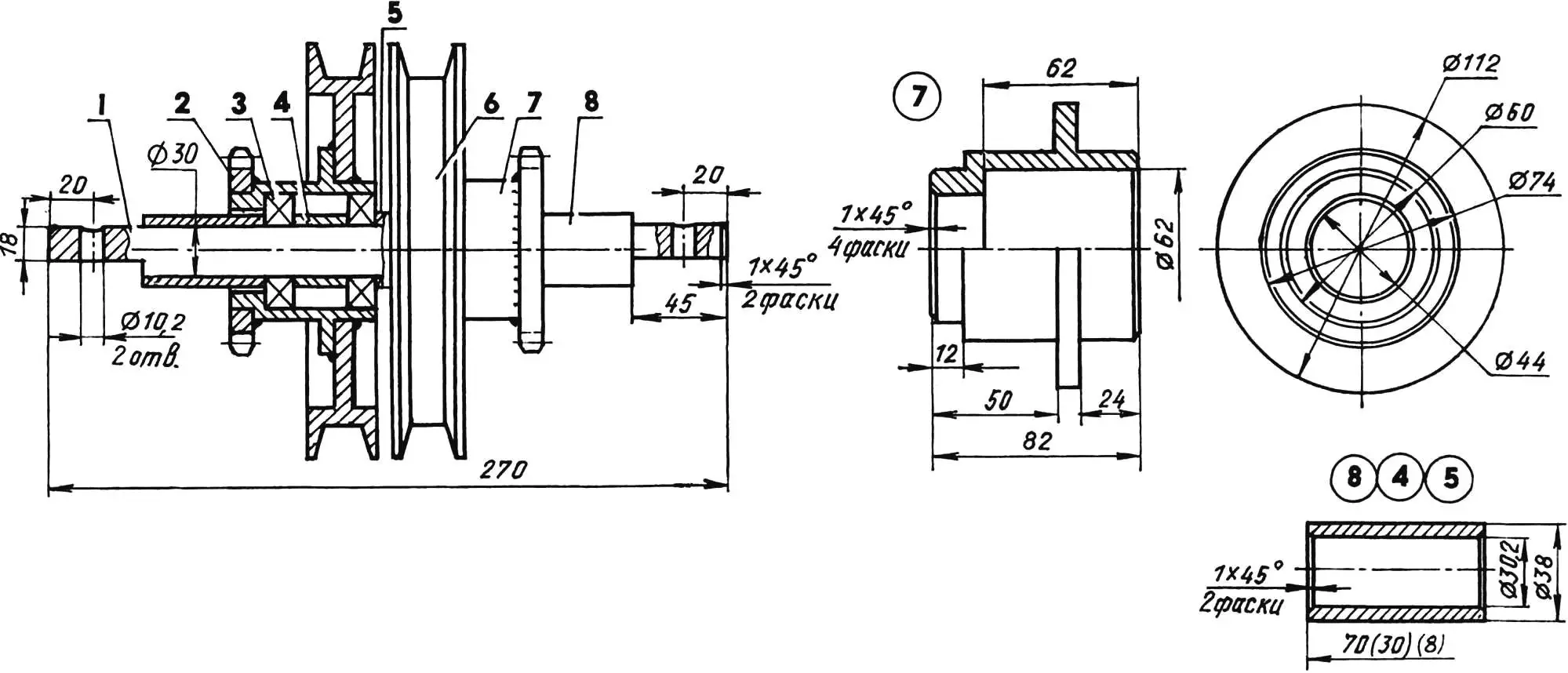
1 — axle (steel, circle 30); 2 — sprocket z=16, t= 19.05 (2 pcs.); 3 — bearing 206 (4 pcs.); 4 — medium spacer bushing (L30, 2 pcs.); 5 — small spacer bushing (L8); 6 — pulley (2 pcs.); 7 — shaft-hub (steel, circle 112, 2 pcs.); 8 — large spacer bushing (L70, 2 pcs.)
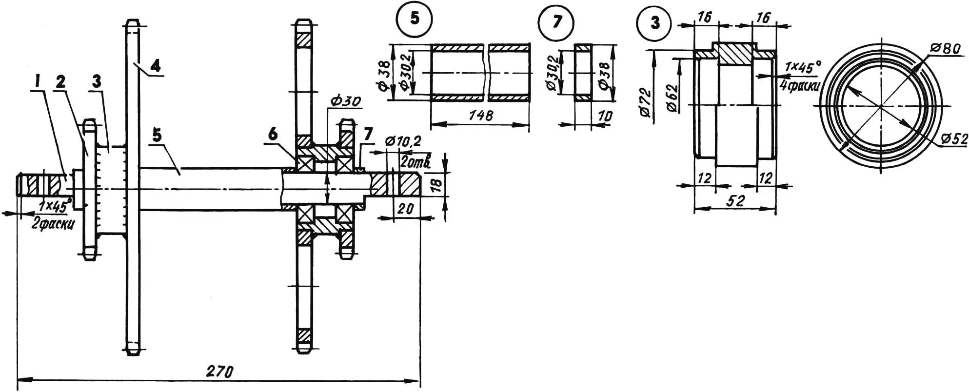
1 — axle (steel, circle 30); 2 — small sprocket (z5=16, t=19.05, 2 pcs.); 3 — shaft-hub (steel, circle 80, 2 pcs.); 4 — large sprocket (z = 50, t = 19.05, 2 pcs.); 5 — large spacer bushing (steel, pipe 38×4); 6 — bearing 206 (4 pcs.); 7 — small spacer bushing (steel, pipe 38×4, 2 pcs.)
All transmission units, except the track drive sprockets, are located in the central compartment of the body. From above, they are covered with deck panels made from the same boards as the rest of the cladding, and access to them is unhindered.
The snowmobile steering is original. It combines the steering features of a motorcycle (handlebar), a car (steering rods and levers), and a tractor (slowing down and accelerating track movement on opposite sides). At the same time, the steering is very simple. Side-to-side slowing and acceleration of the tracks is accomplished by the variator with two V-belts. When the steering wheel is turned, through rods and belt-tensioning mechanisms, one belt is additionally tensioned and the other is relaxed. As a result, one belt goes deeper into the movable pulley, while the other rises on the neighboring pulley to a larger diameter. Then the number of RPM on one rigid pulley increases, and on the other decreases—this is transmitted further through the transmission to the tracks, and the snowmobile turns.
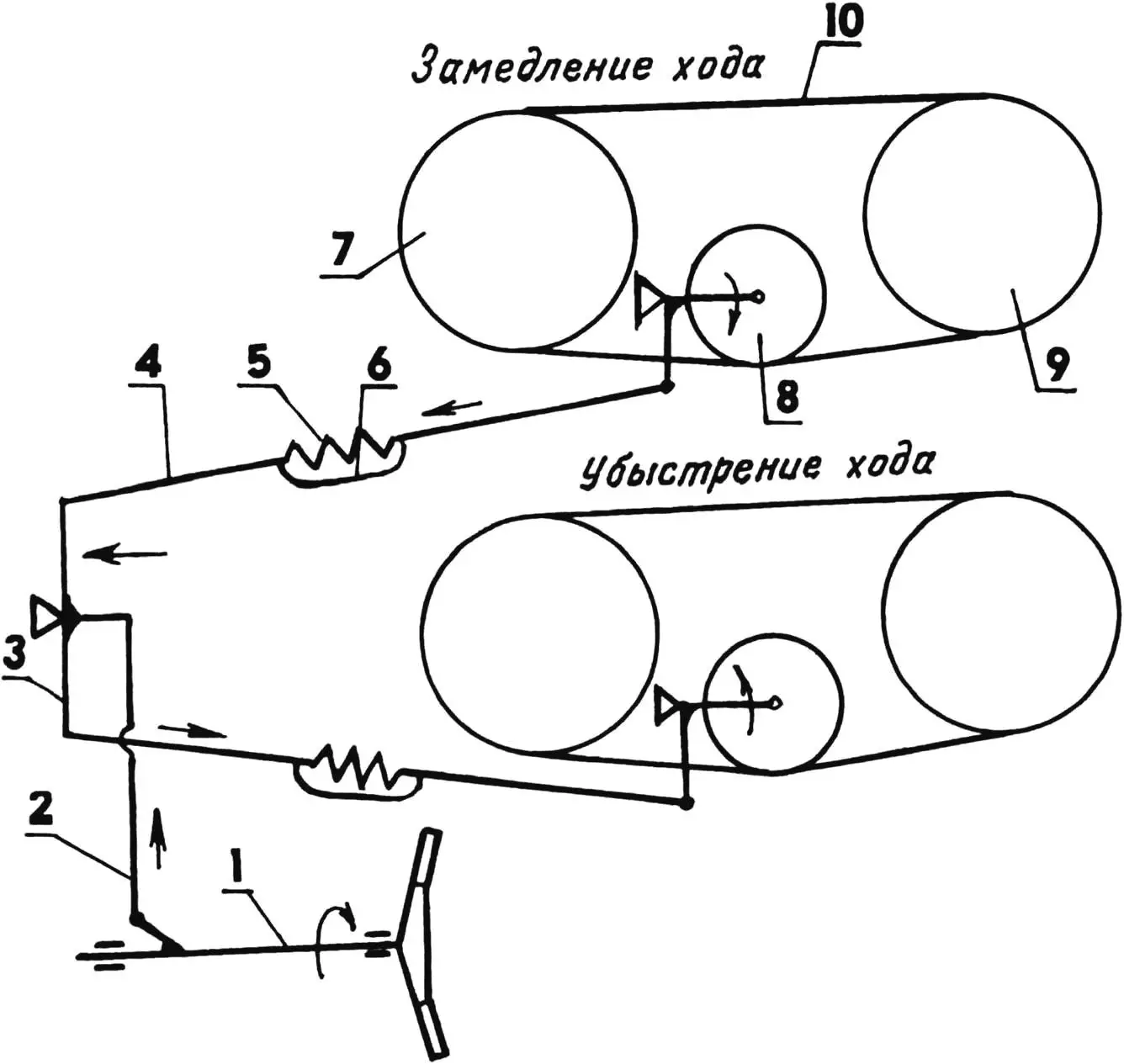
1 — steering wheel; 2 — transverse rod; 3 — bellcrank; 4 — longitudinal rod (2 pcs.); 5 — spring (2 pcs.); 6 — limiting cable (2 pcs.); 7 — movable variator pulley (2 pcs.); 8 — tension mechanism (2 pcs.); 9 — driven variator pulley (2 pcs.); 10 — V-belt (2 pcs.)
When driving straight, the machine doesn’t “hunt”. Several times (out of interest and by necessity) I let the snowmobile run in a “free float” at low speed: I put the steering wheel in the “straight” position and slightly opened the carburetor throttle, then I released it and even stepped onto the platform or walked beside the snowmobile—the vehicle moved evenly and didn’t turn anywhere.
A snowmobile of this design doesn’t burrow into loose deep snow, and it can pull itself out of such “ruts” at small throttle openings (at low engine RPM). It doesn’t overload the weak point of the transmission — the variator with the V-belt drive: the belts don’t slip.
“Modelist-konstruktor” No. 1’2005, V. SEMENOV
Recommend to read
 TRANSCEIVER — TO LIVE LONG
Transceiver SV MJ-2701 company MegaJet is designed for a supply voltage of 12.5 V, which, despite its "special" purpose to work as an automotive MW transceiver with power from the... ZAPOROZHETS ZAZ-968M
Zaporizhia automobile factory was established on the basis of the combine plant "Kommunar" and, apparently, his "rural" origins influenced the design of almost all its cars. The...
