 Designing patterns, usually always takes place in several stages. It is almost impossible to make a decent model, once having passed a way from calculation and drawing to stitched wing Mylar film. Typically, this is only the first step in creating the model. The following will be the flyby of the model and its numerous improvements. And only when to improve the model through modifications, it will be impossible, on paper, a second version of the model, which absorbed all the best from the first and supplemented by all those. it was impossible to implement in the first version, with improvements. This is followed by overflights and…
The proposed readers aerobatic cord models also took place in several steps, unlike the first two steps to simulate the aerodynamic scheme was carried out on simple elektroperedachi — cord of twin-engine aircraft with external power, what is in detail in the journal “modelist-Konstruktor” No. 9 for the year 2003.
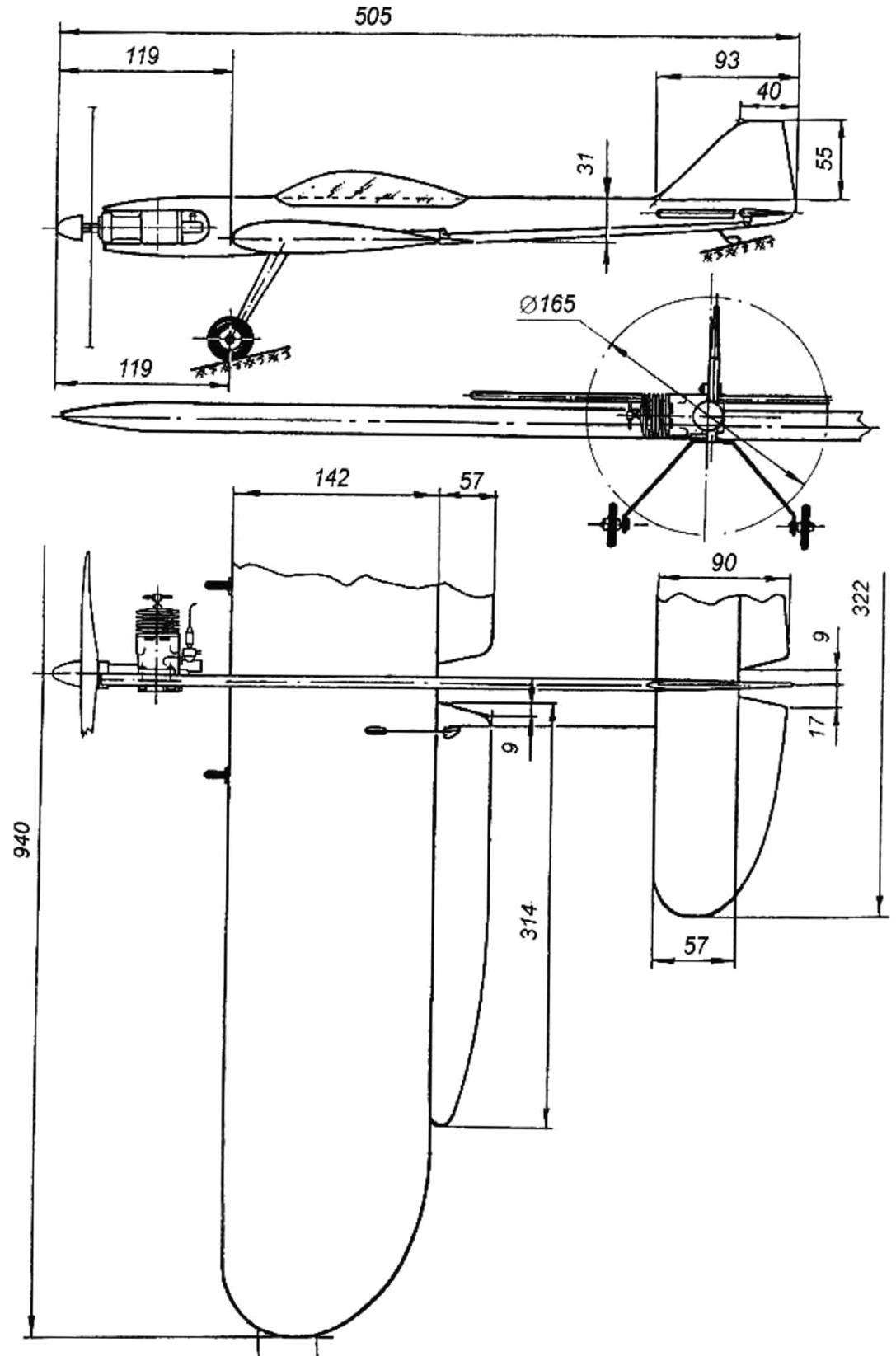
It is elektroperedacha worked out scheme, improved its aerodynamic efficiency and flight properties. The model turned out to be quite interesting, and after not too long the model of service naturally arose the question of the establishment in accordance with the quite successful model of the new, larger model with polutorametrovy diesel MK-17. Preliminary calculations showed that using such an engine it is necessary to increase the wingspan to 940 mm and a fuselage length of 505 mm.
The model is designed according to the scheme of the low wing with a symmetric profile. Design made using balsa, basswood and pine.
The fuselage of the model is flat, it is a frame of pine slats section 3×8 mm, covered on both sides with epoxy using a plywood with a thickness of 1 mm. of the resulting Void boxes, it is desirable to fill with packing foam and it will significantly increase the rigidity of the structure. In the front part of the fuselage glued beech slats and the connecting insert, serving under engine frame.
The keel is fixed, it is cut from 4 mm balsa plate and tightly sealed in the rear fuselage.
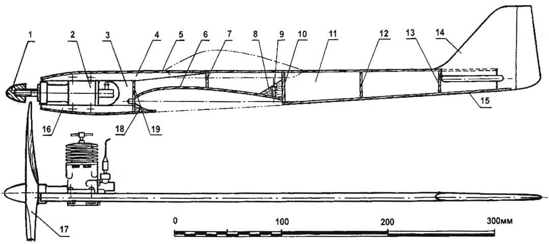
The geometric scheme of the pilot cord model engine MK-17
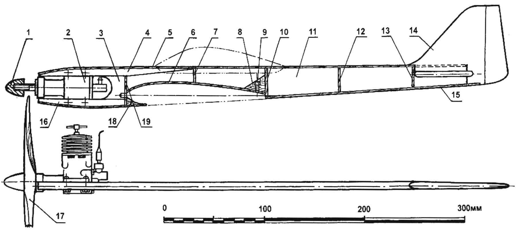
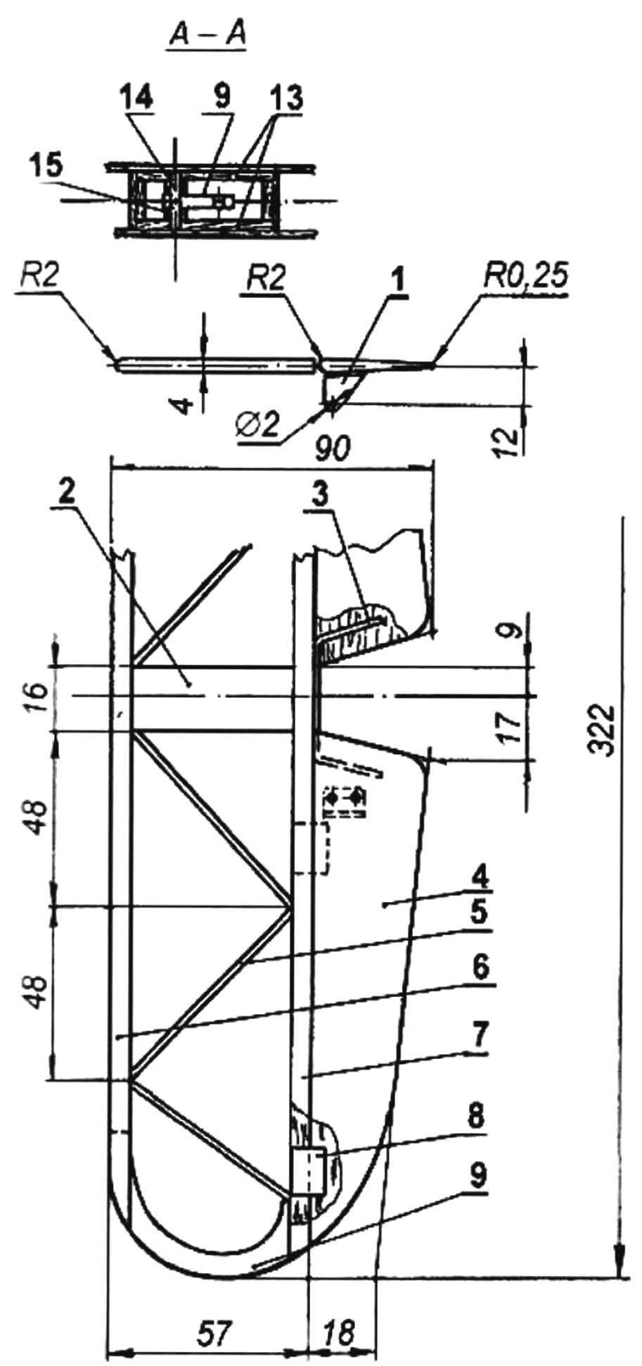
The fuselage of the model:
1 — Kok screw fastening; 2 — the engine MK-17 “Junior”; 3 — insert (beech); 4,16 — bars sub-frame (beech, rake 8×10): a 5.15 longitudinal frame elements of the fuselage (pine, 3×8 rack); 6 — lining of the wing cradle (Linden, plate s2); 7,10,12,13 — cross members of the fuselage (pine, 3×8 rail); 8.18— by boss (Linden); 9 — M3 nut; 11 — side panel of the fuselage (plywood s1); 14 — keel (balsa plate s4); 17 air screw; 19 — baffle (lime)
Purely technologically, the fuselage is better to collect without going under the wing is easier to cut it after curing epoxy glue. Next, the frame was fixed fake boss taped it nut with M3 thread (under bolt wing mounting to the fuselage), and then strip the phony veneer of 2 mm thickness were stuck to the cradle wing.
The front wing fixed to the fuselage using 5-mm beech pin — when docking it is inserted into the opening in the beech insert glued in between the bars of the motor.
Thus prepared polished fuselage skin covered by nitrogenatom and painted with enamel. Lantern “pilot” you can stamp out of thin-walled workpiece, cut from a plastic bottle bluish color.
Horizontal tail inlaid design, it is glued on the Board-the stocks of balsa and fake pieces. The stabilizer was visseren, profiled and covered with a thin colored Mylar film on glue BF-2. The Elevator consists of two blades carved from balsa plates on the stabilizer they hinged like “thermals” or loops from strips of nylon tape. In a single wheel of blades connected by a wire torsion bar.
Wing elektroperedachi stacked, with a veneer of colored Mylar film. Wing profile is symmetrical, Yak-55 (modified with thickened trailing edge), with a relative thickness of 16% — so more suited for pilotage, it has good bearing properties, and it provides a soft and smooth nature of the stall that will simplify piloting.
The wing is assembled on the Board-the stocks in the classic model of technology. The frame consists of balsa ribs with a thickness of 3 mm and a pine front edge of the shelves of the spar and trailing edge. To make the ribs the same, it is recommended in accordance with the table of wing profiles to cut two of the same template sheet duralumin, one of them mark the outlines of the ribs, then parts are cut with a jigsaw with a small allowance, after which a set of ribs with dural patterns outside the package is pulled by a pair of threaded studs and nuts.
The contours of the package are processed by bastard a file with the periodic monitoring of the hull form with a flat metal ruler. The grooves for the spars are cut with a hacksaw on metal. This hacksaw propisyvayutsya grooves for attachment of ribs in the trailing edge of the wing. Wingtips — from lime plate thickness of 3 mm
Frame Assembly being on the Board-the stocks with epoxy glue, slightly diluted with acetone. At the end of the rib right of the console threads and glue is attached a lead weight with a mass of about 20 g. Fuel tank, welded of sheet 0.3 mm thick, fixed between first and second (counting from the plane of symmetry of the model) ribs and the right wing. Wing skin — colored Mylar tape.
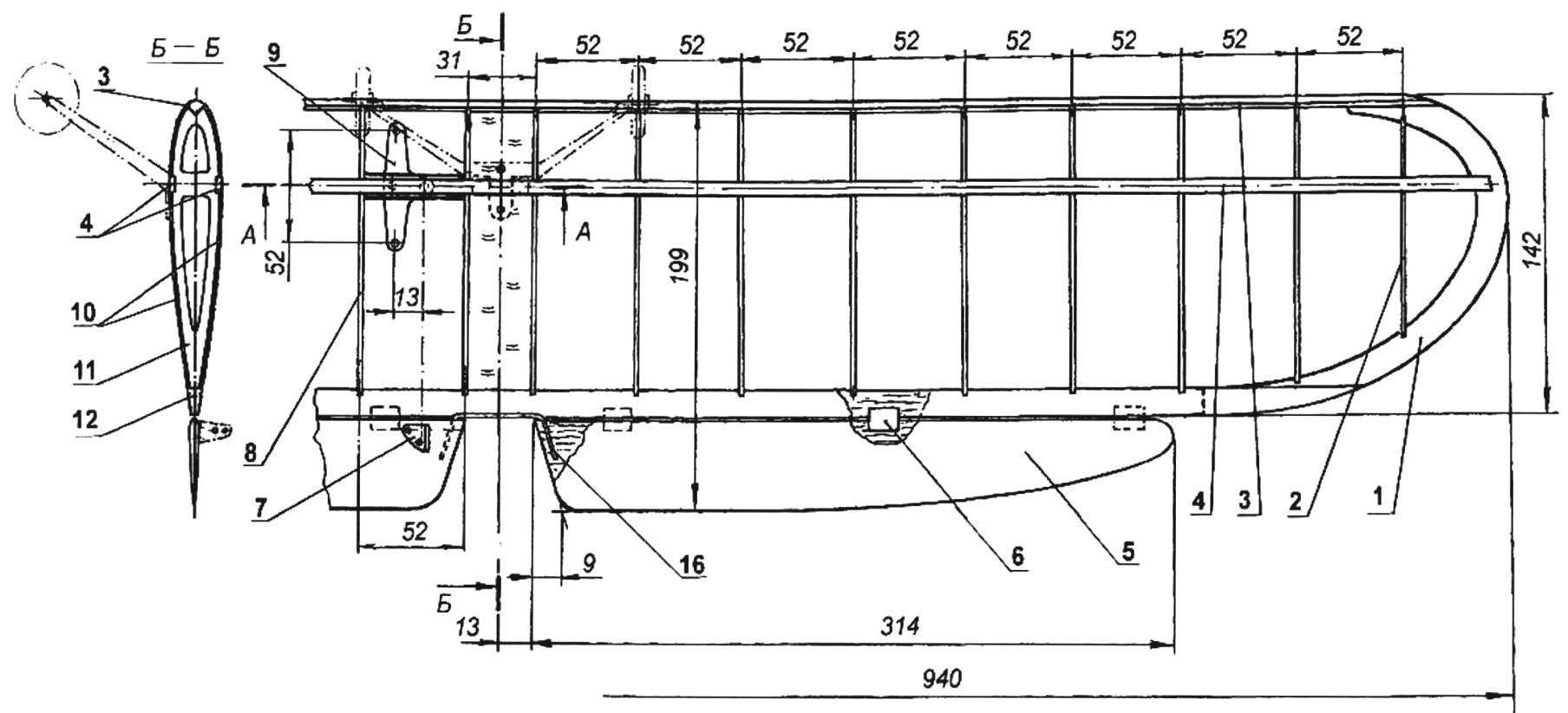
Wing:
1 — ending (Linden, plate s3); 2,8,11 — rib (balsa plate s3); 3 — the leading edge (pine, rail 4×4); 4 — longitudinal splitting (pine, rail 3×6); 5 — flap (balsa plate s3); 6 — loop (nylon webbing); 7 — hog control flap (duralumin, sheet s1,5); 9 — rocking control (duralumin, sheet s2,5); 10 — a lining of the Central part of the wing (Linden, plate s1); 12 — rear flange (pine, rack 6×12); 13 — wall boxes wooden (pine, 3×8 rail); 14 — axis rocking (steel, wire Ø3); 15 — remote bushing (PTFE, 2 pieces); 16 — torsion (steel, wire Ø1,5)
Horizontal tail:
1 — pylon rudder (aluminum sheet s1,5); 2 — Central insert (balsa plate s4); 3 — torsion (steel, wire EOD Ø1,5); 4 — the Elevator (balsa plate s4); 5 — struts (balsa rail 4×3); 6 — the front edge (Linden, rail 4×5); 7 — rear flange (lime, rake 4×4); 8 — loop, nylon webbing); 9 — ending (plywood balsa plates s2)
Rocking control cut from a sheet of aluminum 2.5 mm thick: it is in the box, glued the fake slats, and that — in a niche between the spars, between the first and second ribs of the left wing.
Traction control dural, diameter 2.5 mm, made of needles for knitting an appropriate length.
Flaps — seleblitie, on the wing they hung with loops of the “thermals” or hinges from strips of nylon tape. You can also hang them lacing eight” nylon thread. The flaps are connected in a single body the management of torsion of a steel wire in diameter 1,5 — 2 mm.
Chassis model is a spring cut from a sheet of aluminum with a thickness of 2.5 mm. Wheel chassis, borrowed from a toy car — plastic, with rubber tires; they have a diameter of 32 mm with a width of 12 mm. the attachment of the wheels to the spring — bolt with thread M3 and the corresponding nuts. To the wing of the chassis is secured with two 3 mm screws-screws — in the Central part of the wing glued to this fake bar.
After Assembly, the model must be adjusted correctly. For the learning model, the center of gravity should be located at the point corresponding to 18 to 20 percent of the wing chord, measured from its leading edge by the Way, the measurements of the position of the center of gravity should be performed several times in the Assembly process of the model, facilitating if necessary, certain elements of it. If the alignment is likely to differ from the recommended, you can bring it back to normal with the help of cargo fastened in the front or the rear of the fuselage. For more experienced athletes the model’s center of gravity can be shifted back to 25 — 28 percent of the chord of the wing.
The maximum deflection should be 30 degrees up and down, respectively, the flap deflection of 20 degrees up and down. By the way, at the stage of development of the model the flaps better not to install.
I. SOROKIN
Recommend to read
 BUILDING A CAR
FROM THE ENGINE TO THE WHEELS The transmission from the engine to the wheels can be carried out on a homemade car in different ways. In practice, often such schemes: a)...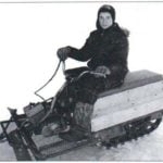 THE FIRST AND EASIEST SNOWMOBILE
The snowmobile, which, the story goes, collected the tenth-grader Sergey Sorokin from the Altai village of Ust-Kamenka. This is not surprising. Equipment guy is fond of since...
