Such machines include a one-wheeled tillers, built our reader from Estonia E. Pabriksom. Self-made frame, gears and suspension helped to create the design of optimal mass and dimensions.
In the “M-K” is not just talked about different designs and the complexity of the tillers. They were mostly two-wheeled options. I think that the homebrew in vain underestimate the dignity of the unicycle scheme. Indeed, such a cultivator is a simple, inexpensive to manufacture and operate, lightweight, and therefore less soil sealing, maneuverable – able to work where two-wheelers do not go, and finally, easy to store – it can be hung up using bracket on the wall. On the other hand, such a scheme places high demands on the layout of units, since the position of the center of gravity of the machine in longitudinal and transverse directions determines the ease of working with it. When installing the engine over the wheel – even of small diameter – the overall center of gravity is pretty high. In addition, with the relatively small mass of the necessary traction wheels with the ground a mere development of the cleats is not achieved. The solution to both problems is to shift the engine forward. This provides the minimum height of centre of gravity and at the same time, there is an allowance of force pressing the wheel down due to the balancing pressure of the operator on the handle. The extra traction helps in the cultivation front of the working body – the horizontal legs having a negative angle of attack.
The location of the working body on the frame is also essential for balancing of the layout. So, when testing with the rear linkage of the cultivator or plow the furrows for direct demanded from the operator a certain skill. Front guns changed the behavior of walking tractor: the wheel was laid on the furrow as a guide, making the beds was obtained as a ruler! Automatically maintaining a constant penetration of the working tool provided with a copying wheel, rigidly connected with the front fork and adjusting rod.
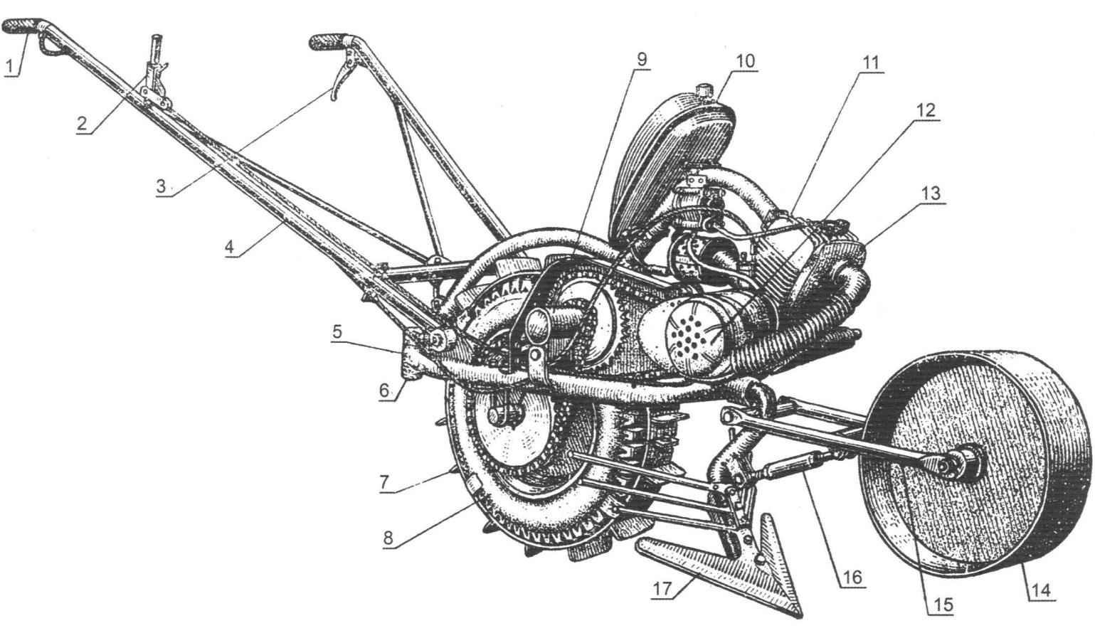
General view of the walk-behind cultivator:
1 – throttle stick; 2 – speed selector lever; 3 – clutch lever; 4 – handle; 5 – frame; 6 – bracket rear hitch work tools; 7 – ground-hooks; 8 – wheel; 9 – an intermediate node; 10-tank; 11 – engine; 12 – fan ring; 13 – baffle cylinder; 14 – gauge wheel; 15 – plug gauge wheels; 16 – adjusting thrust; 17 – paw cultivator
Requirements for engine balancing scheme is also somewhat more rigorous: in addition to the necessary power and cooling, he must have a small weight and dimensions. On my walk-behind tractor has an engine from a moped sh-58. Forced cooling – centrifugal fan, the impeller is mounted via made in the cover plate hole to the flywheel of the engine to the place of installation of the puller. The fan casing is made of thin sheet metal, has a Central inlet and tangential outlet that connects the corrugated hose to the vent on the cylinder. The necessary cooling of the engine can provide and the system with the blower motor on the basis of a DC motor (brand МЭ11 12/5) with the impeller in a metal housing. When side mounted in the edges of the head will need to drill some through holes with a diameter of 15 mm. voltage to the motor terminals is supplied through the diode rectifier mounted inside the fan shroud on the textolite plate, from the winding, lighting maggino you want to rewind a wire of smaller cross section, increasing the number of turns by half.
Frame of thick-walled steel pipe with a diameter of 33 mm. the lateral arc welded from one side in a section of pipe with an inner diameter of 33 mm, oriented horizontally and on the opposite side in the vertical steel sleeve with an outer diameter of 40 mm. the First is for the front installation of the working tool, and the second to be coupled to a two-wheeled trailer. Vertical steel strip 6 mm thick welded in the front part of the frame has the lugs for the engine mounts. The top engine mount welded to the vertical forms the arc of a tubular frame bracket. He also serves as a support for the installation of the fuel tank, borrowed from the bike and the ignition coil of type B-300. On the side arcs of the frame welded fixed plate bracket knobs, stops the wheel axis, bearing housing intermediate shaft and tilt stop tension device. The rear portion of the vertical arc is equipped with lifting eyes for focusing knobs. Two pairs of vertical through holes with a diameter of 8.5 mm at the lateral edges of the frame designed for step ladders – two 11-shaped steel rods threaded at the ends, pressed to stops the axle of the drive wheel.
Frame:
1 – bracket rear hitch; 2 – eyelet threaded focusing control knobs; 3 – mounting plate handle; 4 – the focus of tensioning device; 5 – bracket housing of the intermediate shaft; 6 – arc upper engine mounts; 7 – the attachment of the engine; 8 – sleeve for front attachment of the working tool
The knobs are two steel pipes with a diameter of 25 mm with their ends welded to the sleeve with a horizontal bolt hole M10. Among themselves they are connected by a stretch of a steel rod with a diameter of 10 mm and a transverse tube, which holds the swivel resistant bolt to adjust the position of the handle. In the inoperative position the handle can be folded up. The arrangement of arms and levers of control – as is customary in motor vehicles: right-hand rotary knob is connected with the throttle valve of the carburetor, and the left lever – clutch of the engine. On the right side mounted shifter and rests of shells of ropes. The lever locks in three positions spring lock, which prevents the engine from damage when the spontaneous shifting.
Transmission of tillers is a two-stage chain gear. Torque output sprocket of the engine is transmitted by a chain with a pitch of 15.87 mm on the big sprocket on the intermediate shaft. Both sprocket – wheel transmission of a moped “Riga”. Then with a small sprocket of the intermediate shaft (z=14) is transmitted to the wheel sprocket (z=39). Intermediate node, a shaft mounted on two bearings No. 205 in chiseled steel casing. Since both stars are located on one side of the shaft, for torque transmission, it is sufficient to connect them to the hub by welding instead of locking each of the sprocket on the shaft. The housing of the intermediate shaft connects to the bracket on the hinge to adjust its position in longitudinal and vertical direction. This gives you the ability to simultaneously tension both the chain gears. And in the desired position, the housing is fixed with a tensioning bolt, screw in the tilt stop frame.
Wheel hub drive wheel:
1 – hub bearing (No. 180205); 2 – axle; 3 – body; 4 – the flange of the wheel disk; 5 – star (z = 39, step 15.87 mm)
Intermediate node:
1 – star engine transmission (from a moped “Riga”); 2 – sprocket wheel gear (z=14 step 15.87 mm); 3 – bearings No. 205; 4 – retaining ring; 5 – plugs
Cultivator-Hiller with a copying device:
1 – grating blade Hiller; 2 – paw cultivator; 3 – adjusting sleeve; 4 – jockey wheel
The hub of the drive wheel is machined from a segment of thick-walled steel pipe with a diameter of 60 mm. On the outer surface by welding reinforced sprocket and flange of disk wheels. In the machined ends of the pipe sockets are mounted bearings No. 205. As the side load the wheel hub almost does not feel, for fixing bearings enough resciniti their outer race edge of the nests in three or four points.
The driving wheel may be any, with an outer diameter of 540 mm with a width of 105 mm. this design used discs of 4.50 – 10 rubber scooter of 4.00-10.
The steel lugs of the drive wheel constitute two semi-rings are bent from a strip of 60×5 mm and connected to one side of the hinge, and the other coupling bolt M10. On the outside of the rib 14 welded to the steel strip 30×5 mm, folded at an angle of 45°. To wrap does not come off from the wheel, each of the ends are welded on four side stops. If increased adhesion is not required, cleats are easy to remove from the wheel as they are mounted without decompression and inflating the tire.
The fan impeller. The control handle.
Working tools – cultivators, plow, harrow, dozer blade, Shuttle cart and others-can be installed either behind or before a wheel cultivator. The figure shows the front cultivator with gauge device. The bracket arms of the cultivator is made of thick-walled steel pipe with a diameter of 33 mm. the pipe bending is not crushed, this operation must be performed in a heated condition, after filling the internal cavity with sand. Mounted on the lower end of the bracket paw provides the cultivation of the soil without flipping it, and welded above the blade lattice of steel rods with a diameter of 10 mm performs the function of Hiller.
The ability to adjust and precise depth of tillage is achieved by a copying unit, consisting of a welded steel strip wheels, forks, bearing its axis, is attached to the bracket of the working body and the adjusting rod. Up its sleeve – a tube with a diameter of 22 mm, internal thread M12 on one side – right, another-left. Two rods with the appropriate thread connects the plug to the wheel through the grommet with the bracket. Thus, rotation of the sleeve in either direction changes the length of the thrust, and hence the position of the gauge wheels relative to the working tool.
E. PEDRIKS
Recommend to read EGLOMISE: TOOL-UNIVERSAL The article "Acupuncture for metal", published in the journal "modelist-Konstruktor" No. 2, 1974, provoked numerous responses, not only individual readers, but also many businesses and... “BOTTLE” HANGER The journal "modelist-Konstruktor", according to my calculations, for a long time can already be entered in the "Guinness Book of world records" for number of published articles on...
Scroll back to top

 Among the variety of tillers, microstructural and any other motor vehicles dominate Amateur-built machines, assembled from serial components and assemblies. The selection of a standard motor for most cases it is justified and necessary. But the use of ready-made frames, rear axles, transmissions, gearboxes, clutches almost always makes the homemade is too heavy, bulky and unsightly. A more promising design concept – using the minimum required number of standard units. Such mechanisms, although more laborious to manufacture, but allow the author to realize the most daring design ideas.