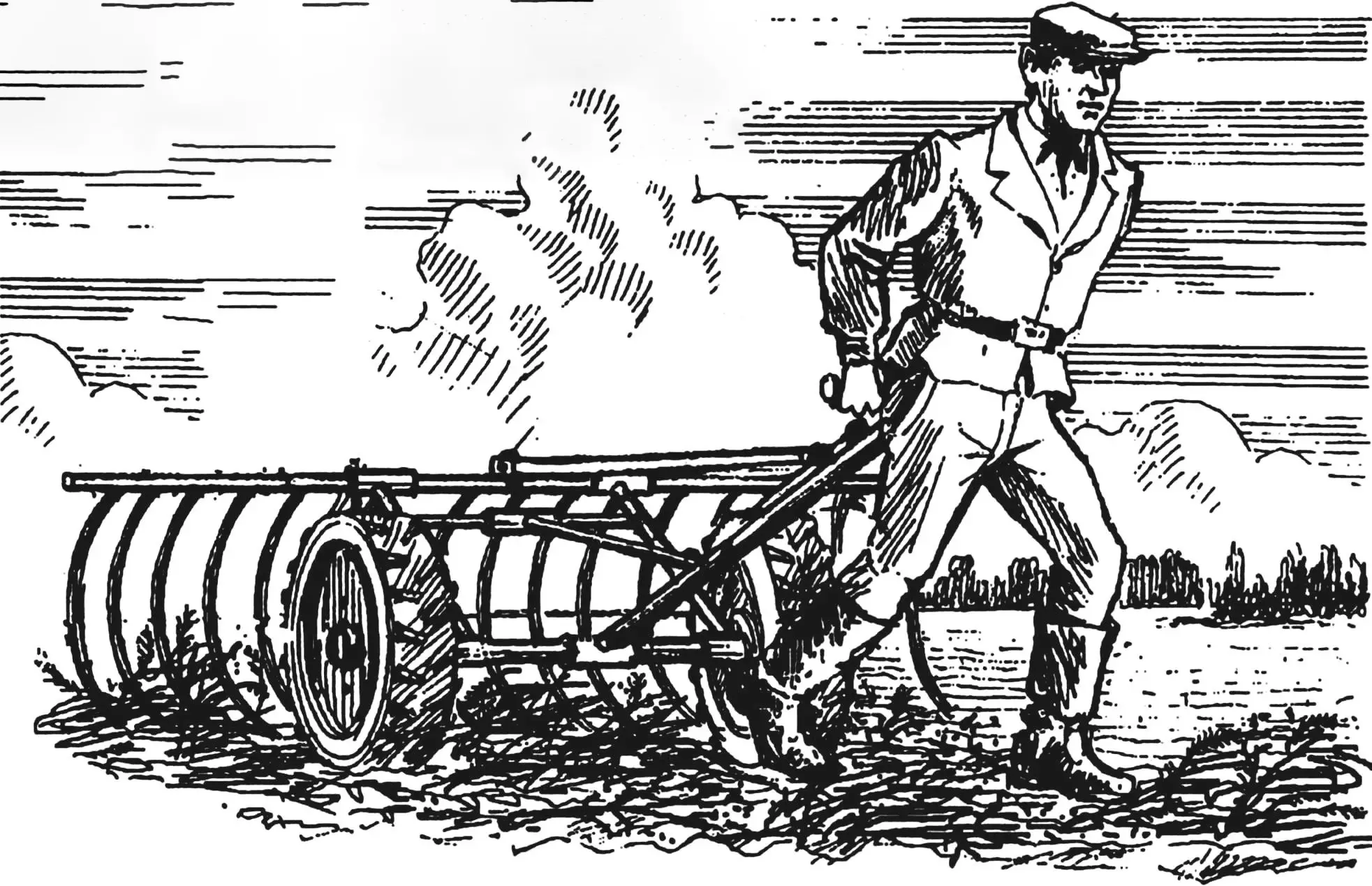
Ordinary hand rakes for hay collection are an ancient tool familiar to every rural resident. As a rule, all parts of this tool are made of wood to make it lighter—after all, you have to hold it almost always in the air during work. The width of hand rake capture is small, and accordingly, productivity is low even for agile collectors.
Haymaking season is the time when bad weather is not just a hindrance to work, but also a disaster. Rain is the worst enemy of mowed grass. If it soaks it, the hay will not only lose its valuable qualities but may also be hopelessly spoiled. The saddest thing about this is that losses can most often simply not be recovered.
Peasants during haymaking, as soon as they see a cloud on the horizon, rush to rake the mowed grass into haystacks and haycocks and, if possible, cover them with tarpaulin or polyethylene film on top. But haymaking lands are always significant in area, and even several very agile workers cannot always quickly (before rain) collect drying grass with ordinary rakes.
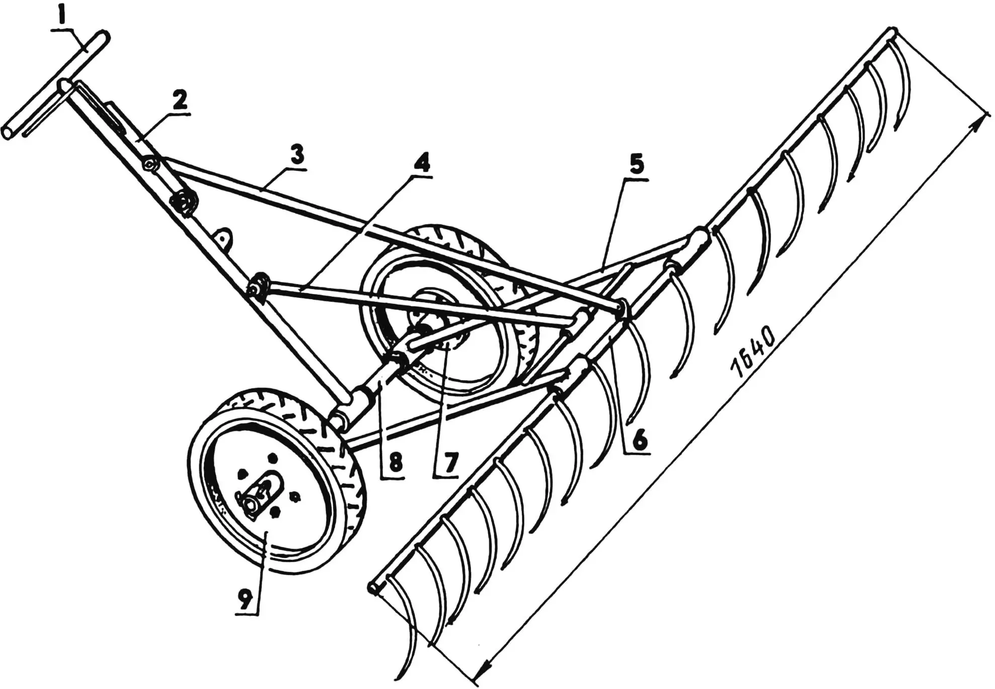
1 — drawbar; 2 — lever; 3 — rod; 4 — strut; 5 — post; 6 — rake; 7 — hub; 8 — axle; 9 — wheel (from KRN cultivator)
To avoid dooming hay to spoilage under such conditions, I made mechanized (though hand-drawn) wide-capture rakes. The main material for them was water pipes of various diameters. Since the diameter of such pipes is usually measured in inches, I will not deviate from this rule when describing the rake design. I’ll just remind you that this size is relative and shows not the outer diameter of the pipe, but rather the hole in it, though also approximately. This size is called the nominal diameter. For example, a half-inch pipe has an outer diameter of 21.3 mm, and an inner diameter (clear size) of 15 mm (although, as is known, 1″ equals 25.4 mm, which means 1/2″ is 12.7 mm). But these diameters can also vary slightly depending on the wall thickness of the pipes.
This circumstance forced me to select pipes as material for making rake parts in such a way that the outer diameter of some mating elements matched the inner diameter of others.
| Nominal diameter | Outer, mm | Inner, mm | |
|---|---|---|---|
| inches | mm | ||
| 1/2″ | 15 | 21.3 | 15.7 |
| 3/4″ | 20 | 26.8 | 21.2 |
| 1″ | 25 | 33.5 | 27.1 |
But even after such selection, some parts did not fit into others without a gap. Then I put the bushing on a steel cylindrical rod and tapped its surface, turning it over and over. The same operation for slightly increasing the inner diameter of the bushing can be performed with a suitable round or half-round file.
When making rakes, in addition to the usual locksmith tools: hammer, hacksaw for metal, electric drill with a set of drills, electric welding was required. I had it. Therefore, some units that could otherwise be made detachable with fasteners, I made non-detachable, welded—it was easier for me.
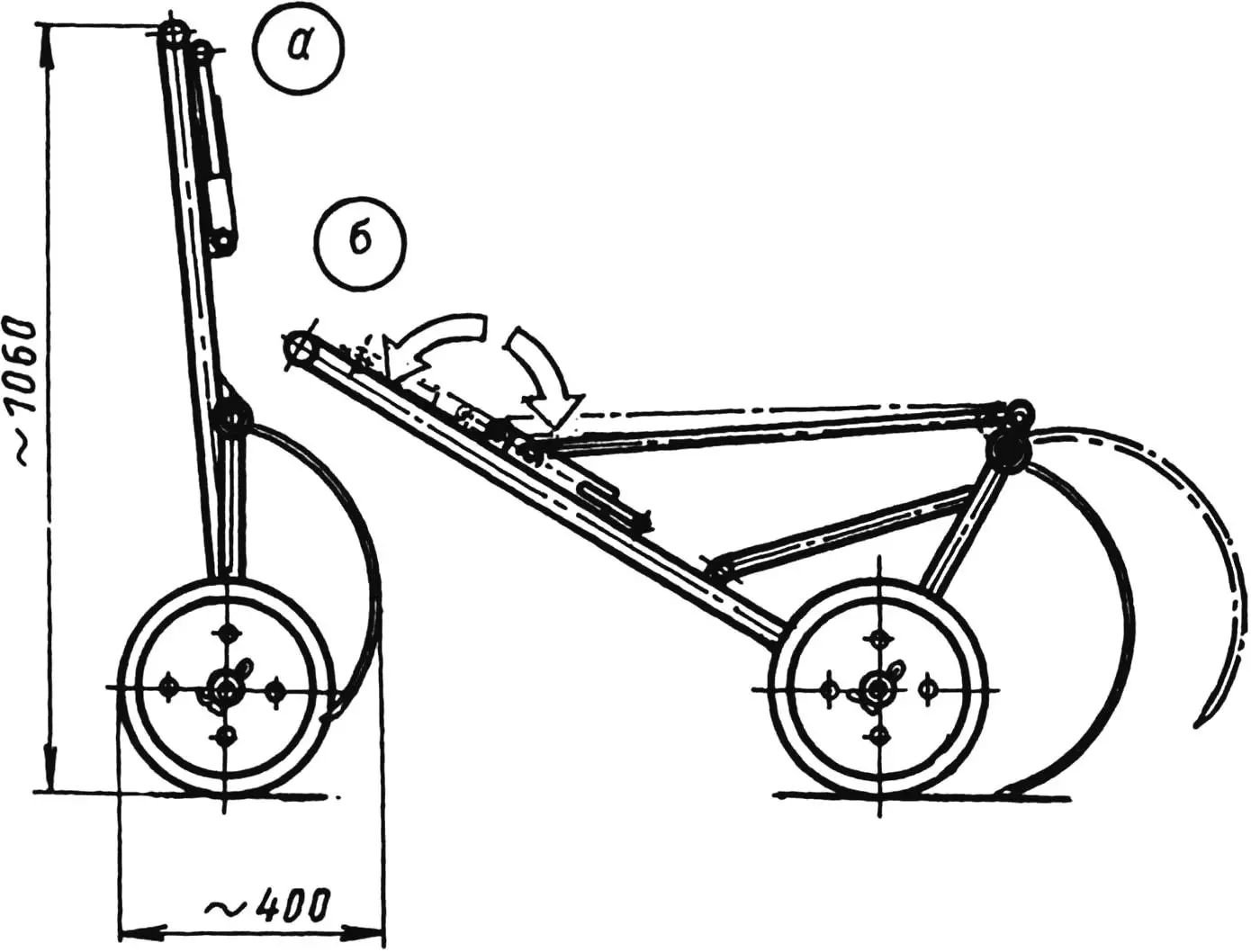
a — in transport position; b — in working position
The design resembles horse-drawn rakes, only their dimensions are smaller and the device is simpler. I achieved simplicity by mounting rotating and even revolving parts (wheels) on their axles without rolling bearings, as the latter would significantly complicate the product. For convenience of transporting rakes from the mowing site together with hay, I made the structure foldable.
Making similar rakes according to the provided drawings will not cause great difficulties for a craftsman who knows welding. But I will still note some features of their manufacture.
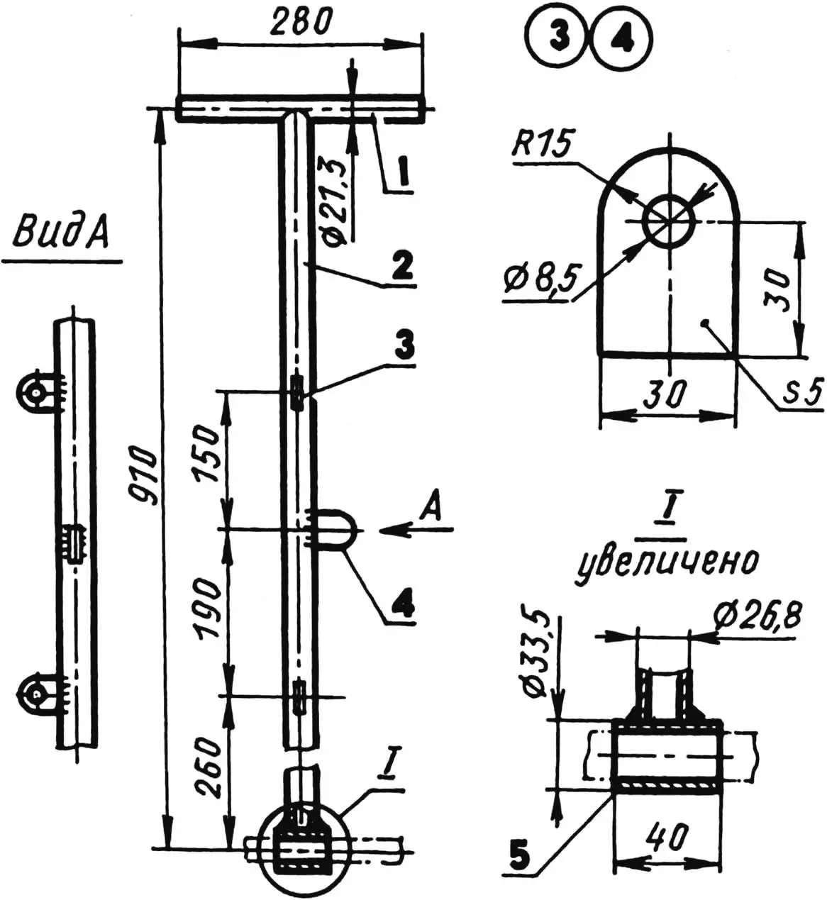
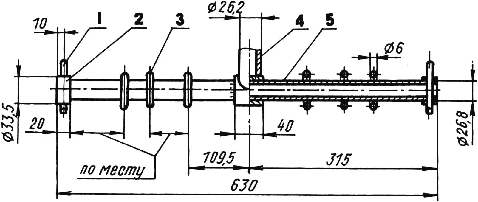
1 — handle (pipe 21.3×2.8); 2 — drawbar (pipe 26.8×2.8); 3 — bracket (St3, sheet s5, 2 pcs.); 4 — stop (St3, sheet s5, made with dimensions of item 3 without hole); 5 — transition bushing (pipe 33.5×3.2)
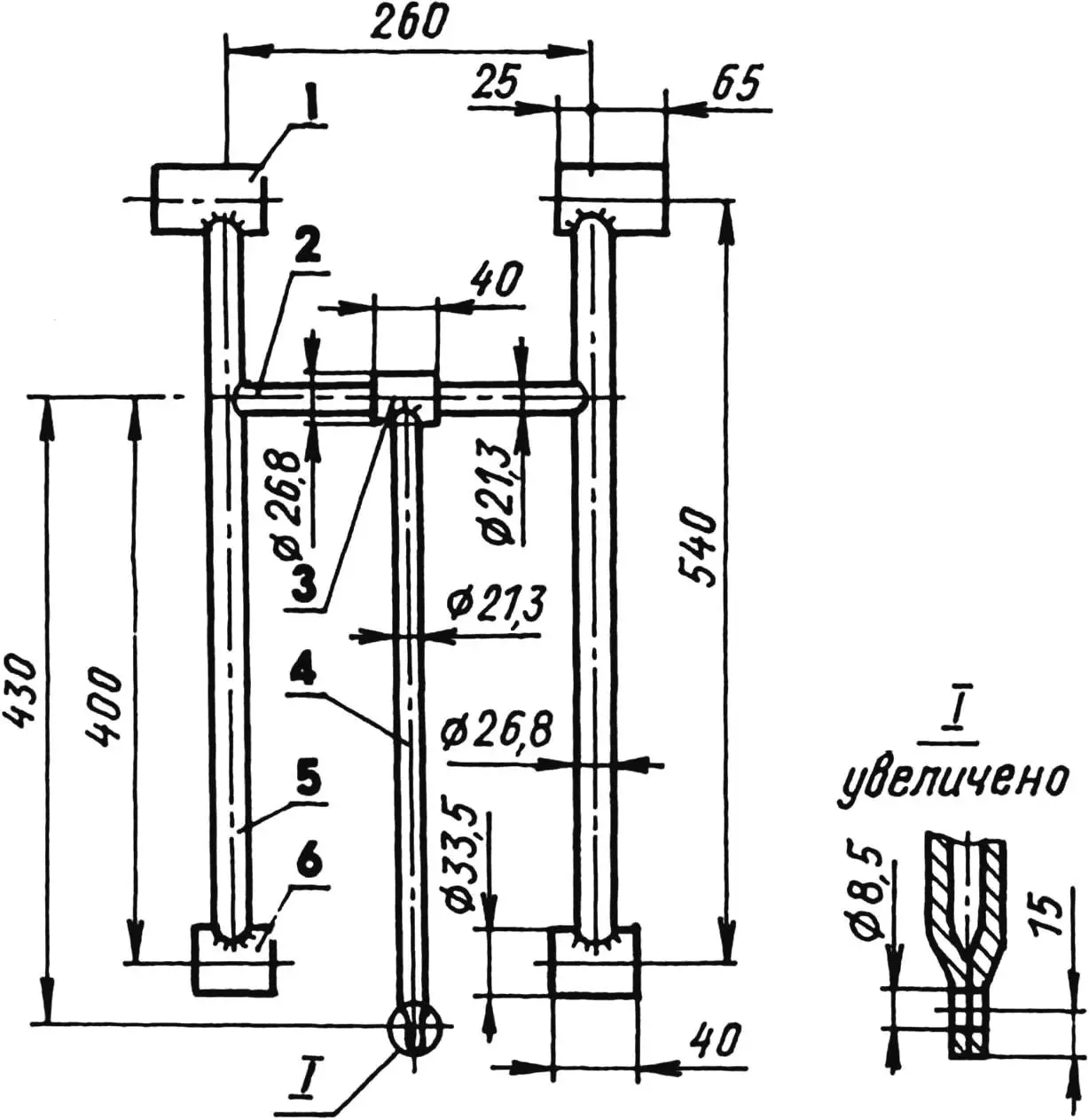
1 — bushing (pipe 33.5×3.2, 2 pcs.); 2 — crossbar (pipe 21.3×2.8); 3 — crossbar bushing (pipe 26.8×2.8); 4 — strut (pipe 21.3×2.8); 5 — leg (pipe 26.8×2.8, 2 pcs.); 6 — bushing (pipe 33.5×3.2, 2 pcs.)
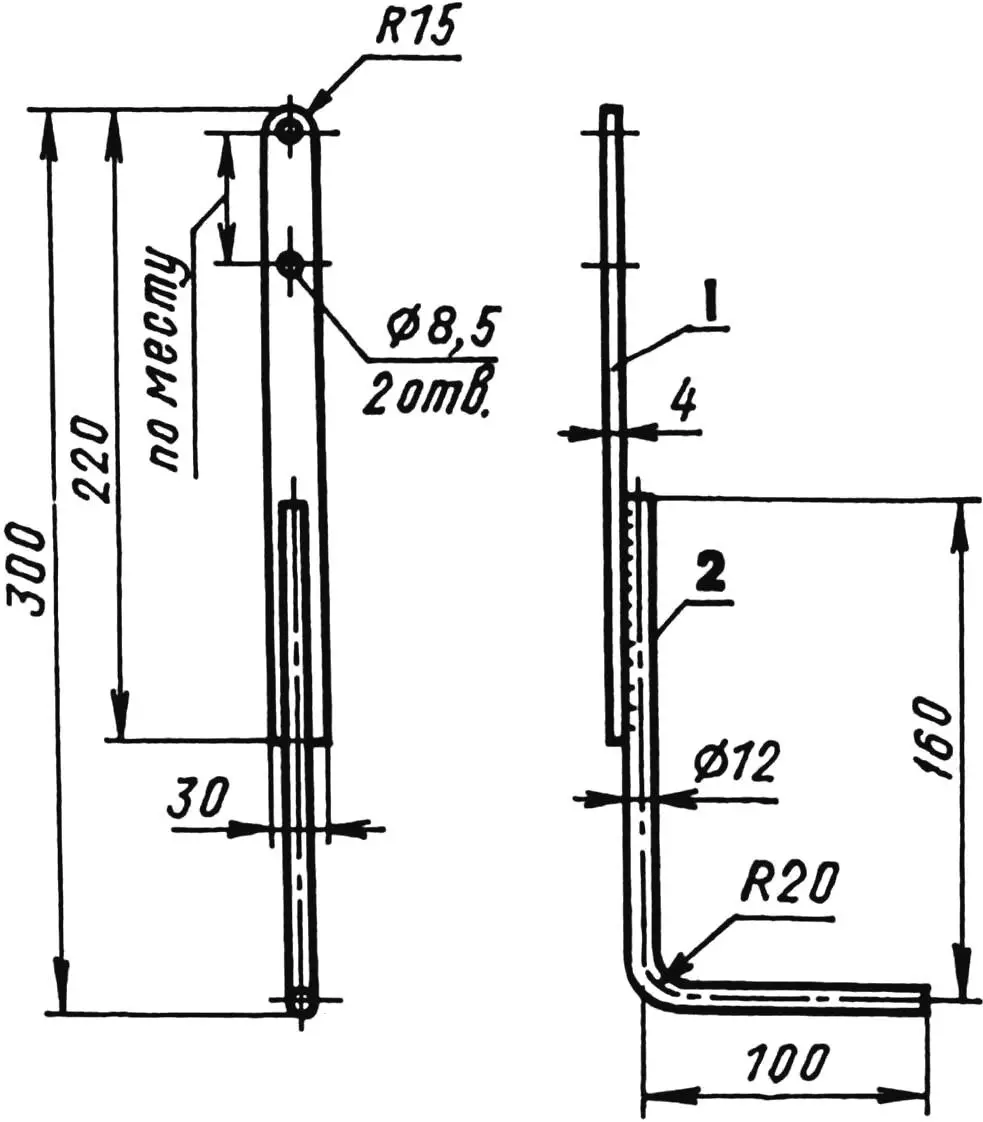
1 — lever (St3, strip 30×4); 2 — handle (St3, rod Ø12)
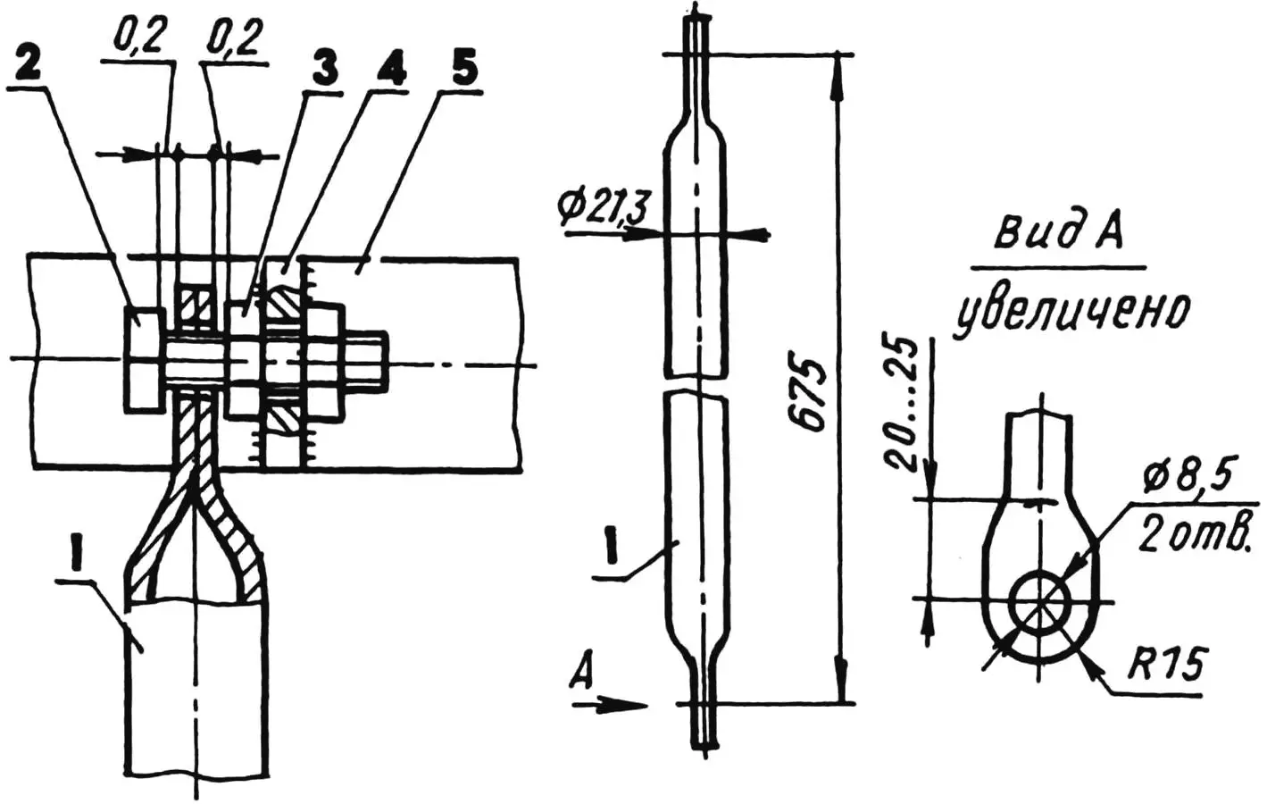
1 — rod (pipe 21.3×2.8); 2 — bolt M8; 3 — nut M8 (2 pcs.); 4 — bracket; 5 — rake console
Drilling holes for teeth in the rake console pipe is best done on a machine. Then you can immediately drill holes with a diameter of 8 mm. The axes of the holes in this case will be guaranteed to be parallel to each other and lie in one plane. I didn’t have a machine, and I performed this operation in two passes—the first with a 4 mm diameter drill, trying to maintain the parallelism of the hole axes as accurately as possible.
For the hinged connection with the lever and rake console, I flattened both ends of the rod, drilled holes here, and ground the ends to a radius. I did the same on one end of the strut.
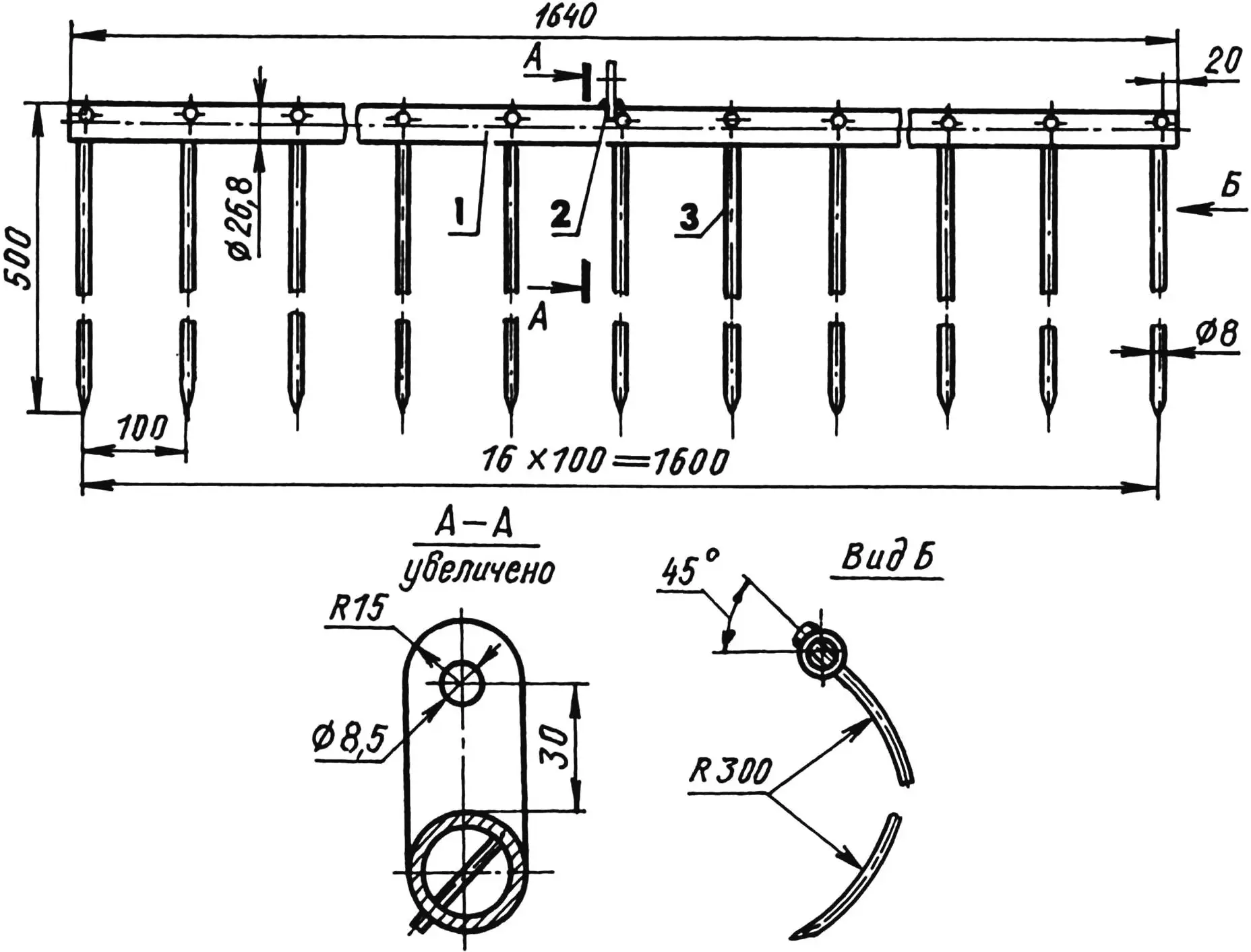
1 — console (pipe 26.8×2.8;); 2 — bracket; 3 — tooth (steel 45, rod Ø8, 17 pcs.)
Before welding parts with bushings, I processed the ends of the first along the arc of the outer diameter of the second. By the way, the drawbar can be welded to the axle without a transition bushing.
Before welding the posts to the crossbar, the strut bushing should be put on. When making rakes, before installing the teeth in the console holes, the upper post bushings must be put on the latter. One bushing should be placed between the 7th and 8th teeth, the other—between the 10th and 11th. The lower post bushings on the axle should be put on simultaneously with the drawbar bushing. The drawbar bushing is welded to the axle. The displacement of the post bushings along the axle should be limited by welding wire rings (from two half-rings) to it next to the bushings. The same rings limit the inward displacement of wheels with a diameter of 300 mm from the KRN cultivator (others will also work, but with a diameter of up to 500 mm, otherwise you will have to increase the dimensions of other units and parts). Outside the wheels on the axle, thrust rings from an inch pipe are installed and cotter-pinned.
1 — cotter pin 6.3×45 (2 pcs.); 2 — thrust ring (pipe 33.5×3.2, 2 pcs.); 3 — limiting ring (consists of two half-rings) (rod Ø6, 6 pcs.); 4 — drawbar with transition bushing; 5 — axle (pipe 26.8×2.8)
Some difficulty may be presented by choosing the location of the second hole on the lever for the upper end of the rod. Its location must correspond to the travel of the rod with the bracket on the console from the raised position of the rakes to the ends of the teeth lowered to ground level.
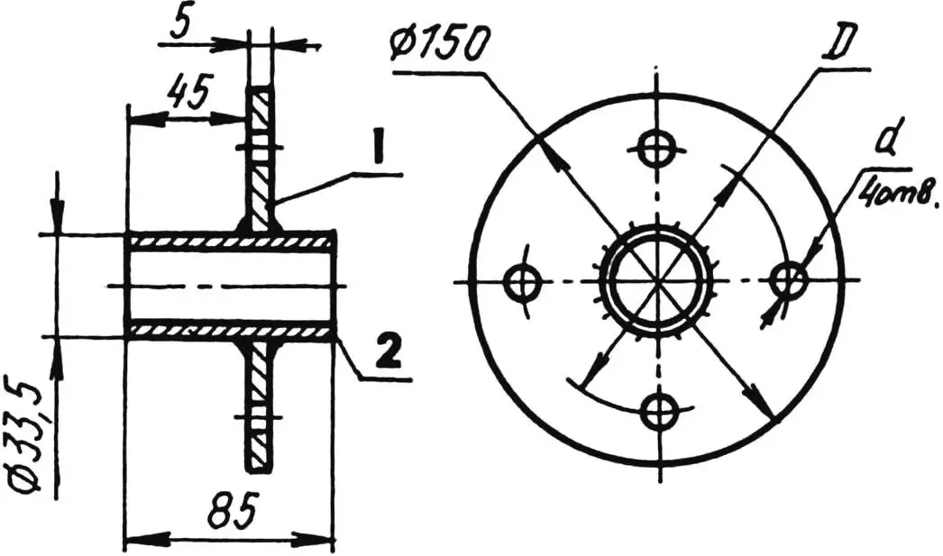
1 — disk (steel 45, sheet s5); 2 — bushing (pipe 33.5×3.2);
D and d — according to holes in wheel disk
Each hinged connection consists of a bracket, an M8 bolt with two nuts, and a moving part (end of the rod or lever). The middle nut is fixed by crushing the thread in a position that provides a small gap between it and the moving part. Instead of a second hex nut in each hinge, a wing nut can be used—then a wrench won’t be needed. I use these same hinged connections when folding the structure for transport. To do this, I unscrew the outer nuts on both ends of the rod and the lower end of the post strut.
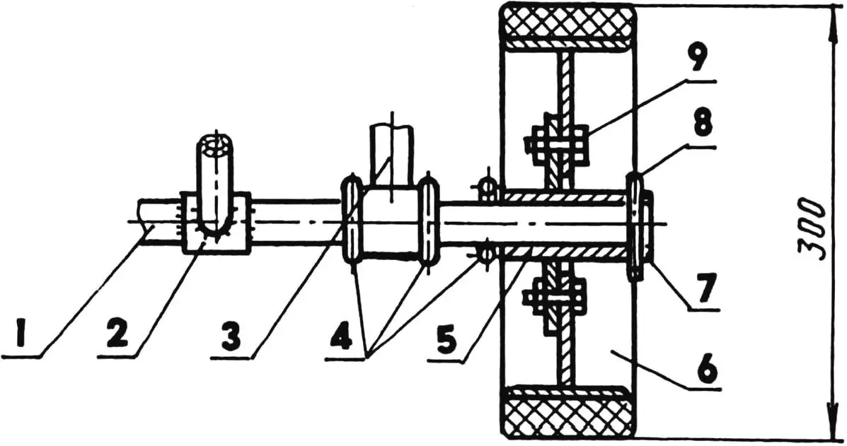
1 — axle; 2 — drawbar with transition bushing; 3 — post with bushing; 4 — limiting rings (each from two half-rings); 5 — hub; 6 — wheel (rim and disk) with tire; 7 — thrust ring; 8 — cotter pin; 9 — wheel mounting bolt
The overall dimensions of the rakes in the folded (transport) position are 1060x400x1640 mm. Despite the fact that all parts are steel, the rakes turned out not so heavy—their mass is only 20 kg.
The rakes are most effective at hay dry matter yield of up to 15 centners per hectare when mowing grass with various hand mechanized mowers or using walk-behind tractors. At higher yields, the length (height) of the rake teeth should be increased to 700—800 mm. Using the rakes allows raking hay into windrows from an area of 0.5 ha in 1 hour of work with minimal losses. Such rakes are not difficult to adapt for mechanical traction.
«Modelist-Konstruktor» No. 8’2003, A. KOSTERENKO
Recommend to read
 Both in the attic and in the garden
In dacha conditions, especially if it is a new build and everyday life is not yet settled, the proposed design will prove as necessary as it is versatile. Quick and simple to make, it will...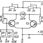 A simple voltmeter
measuring constant voltage value of 100 V. It is produced by the bridge circuit for the transistors T1 and T2. In one diagonal bridge included a measuring device in the other power...
