
When building country cottages or garages on a homestead, you often need to screen bulk construction materials, soil, or garden earth. For this, a special fixture is used — a so-called vibrating screen (grizzly). Its classic version — a frame with a mesh set on trestles — is very bulky and low-productivity. I tried to make it mechanized, and also more compact and quieter than industrial samples.
My first electric screen turned out not entirely successful. However, the second, improved one met all the planned requirements. Manufacturing it required neither scarce materials nor a highly skilled maker.
The design consists of a base, uprights, a frame with an electric motor, braces, and tie rods. The dimensions shown on the drawings are approximate and may be changed according to local needs and capabilities.
The base comprises two hollow bars, each made of two boards joined through spacers. Holes Ø14 mm are drilled in the base bars.
The two inclined uprights are bars of 60×80 mm cross-section. At one end of each bar a Ø14 mm hole is made, and at the other a slot. The uprights are inserted between the base boards and fastened with studs and M12 nuts.
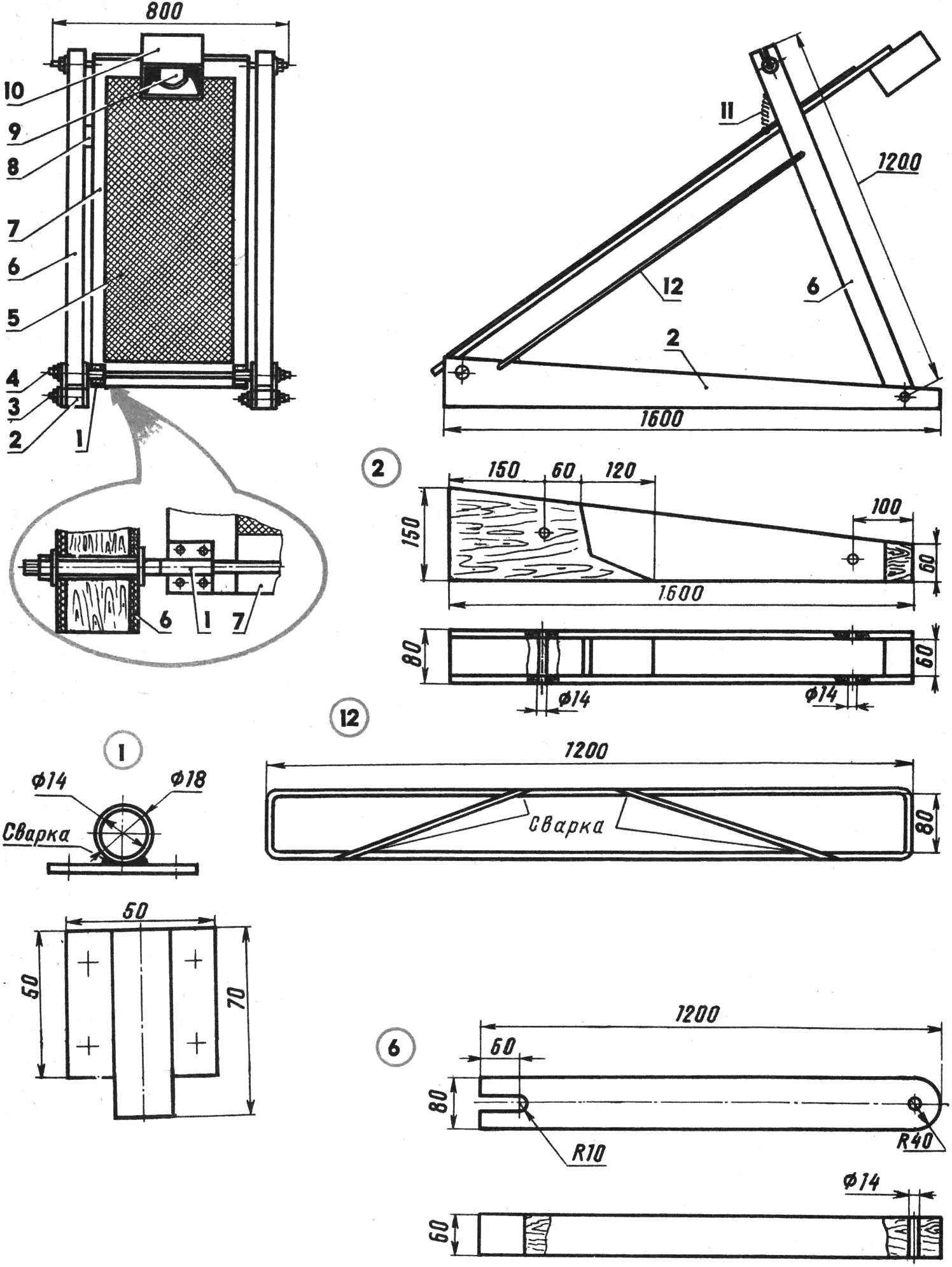
1 — bracket (2 pcs.), 2 — base (2 pcs.), 3 — M12 stud (2 pcs.), 4 — tie rod (2 pcs.), 5 — mesh, 6 — upright (2 pcs.), 7 — frame, 8 — automatic switch, 9 — electric motor, 10 — protective cover, 11 — spring (2 pcs.), 12 — brace (2 pcs.).
The frame is assembled from bars whose lengths are chosen according to the size of the available mesh, and the cross-section according to the expected load. Using brackets, the frame is mounted on the lower tie rod. It is suspended from the upper tie rod on a spring.
The electric motor (from a Buran vacuum cleaner) is fastened to the upper edge of the frame and enclosed by a cover. The cover is essential. It protects the motor from soil getting onto it and, for safety, also guards the rotating shaft eccentric. To keep screened material from spilling sideways, side boards are nailed along the frame.
To give the structure oscillating motion, I rejected a ratchet gearbox because of the complexity of making it and the strong noise it produces. Vibration is created by unbalancing the motor shaft. The eccentric is made from an ordinary wooden block. By selecting its shape and weight, the required frequency and amplitude of oscillation are obtained.
The braces (to stiffen the structure) are made of wire 6…8 mm in diameter; the tie rods and studs are made of rod with M12 thread at the ends.
While further modernizing the unit, I fitted the screen with a device that automatically switches the motor on or off depending on the load on the frame. This eliminates idle running, saves electricity, and increases the overall life of the structure.
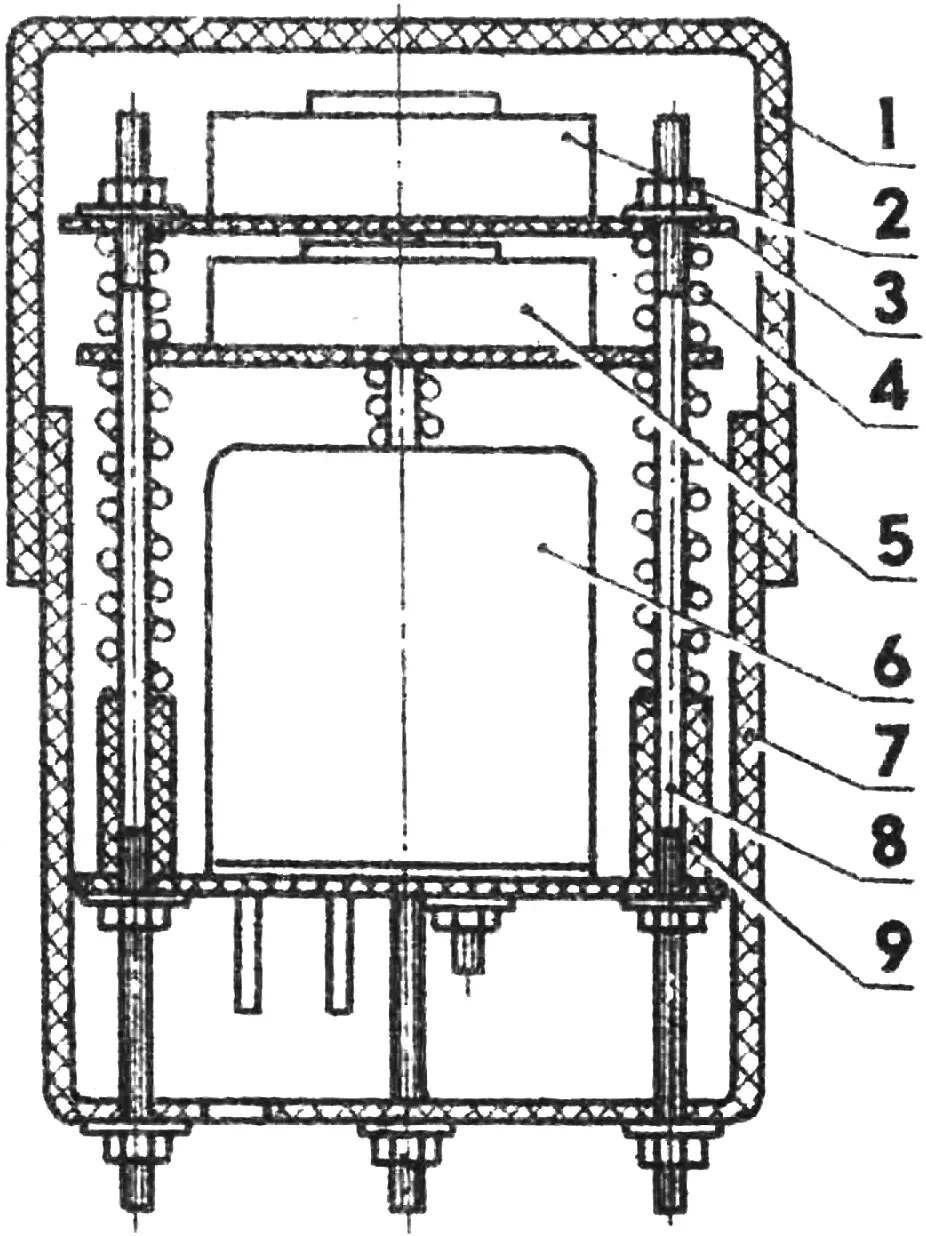
1 — cover, 2 — button S1, 3 — board (PCB laminate, 3 pcs.), 4 — spring (6 pcs.), 5 — button S2, 6 — MKU-48 relay, 7 — housing, 8 — M4 stud (3 pcs.), 9 — bushing (3 pcs.).
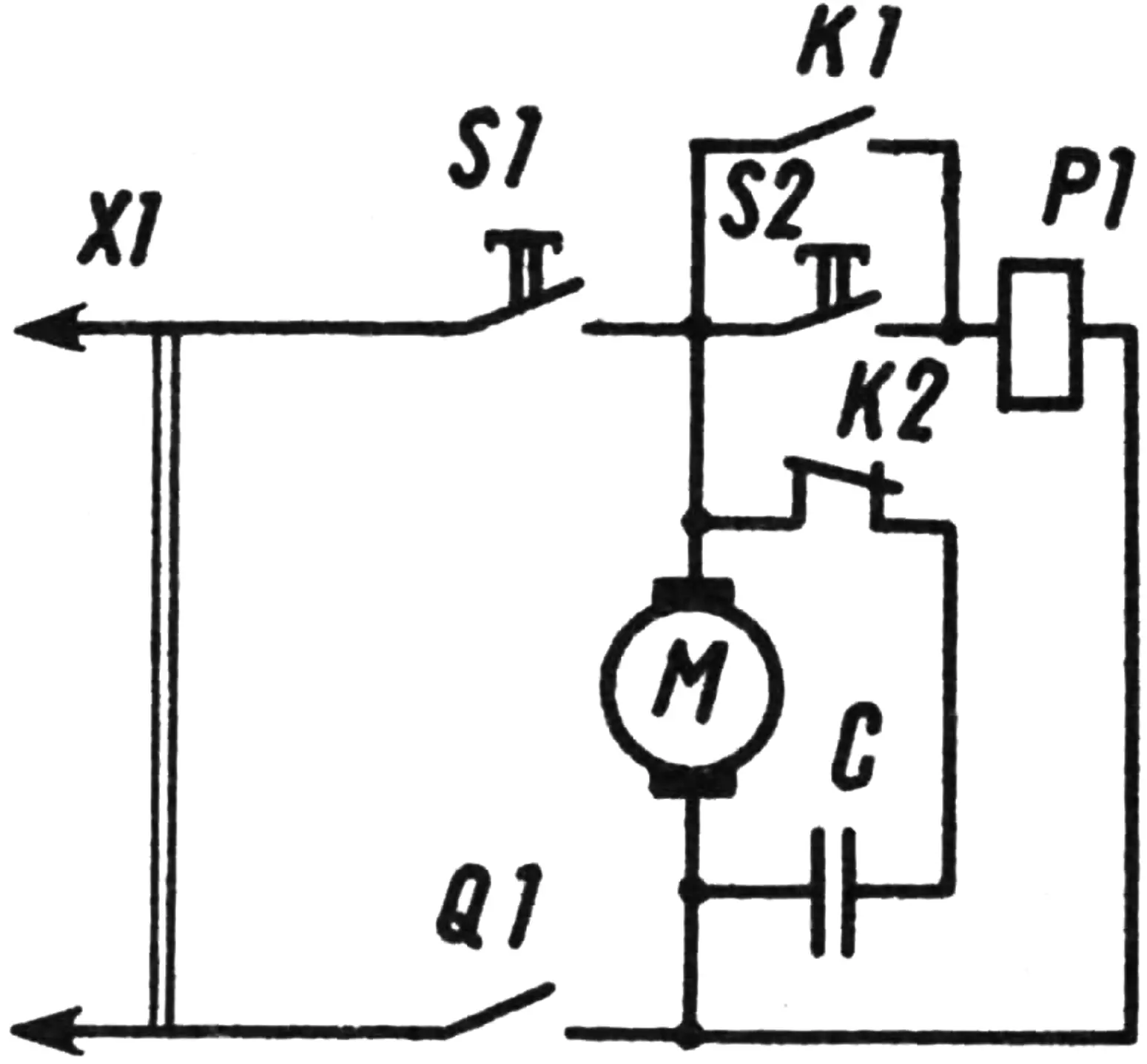
The “automation” works as follows. When the frame is loaded, it drops down and presses button S1. Its contacts close the motor circuit. The motor starts rotating and shakes the frame. At the first “dip” of the frame caused by vibration, it presses button S2. That in turn closes the supply circuit of the electromagnetic relay, which self-latches with contacts K1 and, with contacts K2, disconnects the motor’s excitation (starting) winding. Thanks to the relay’s self-latching, the starting winding stays disconnected throughout the work cycle. After the material has been screened, the load is removed from the frame. Springs pull it up and open button S1. The circuit returns to its initial state.
The buttons and the relay are mounted on three boards. Between the boards of buttons S1 and S2 there are two springs that soften impacts and keep the contacts closed while the frame is loaded; between the board of button S2 and the relay there are four springs needed for a later closing of S2 contacts and for protecting them from mechanical damage under vibration. The unit uses ordinary doorbell pushbuttons and an MKU-48 relay (or any other relay rated for 220 V). The springs were taken from a garden pruning shear. The housing is made from cut-down shampoo bottles. By selecting their diameter, the required weather protection can be obtained. The automatic switch is fastened (with clamps) to one of the uprights. This method allows the closing time of button S1 to be adjusted according to the load.
The screen is stored disassembled indoors, protected from moisture and snow.
To those who want to build a similar fixture, based on two years of operating my screen, I want to give a few tips. First, the power wiring from the automatic switch fixed on the upright to the motor mounted on the frame is best routed via the lower edge of the frame. Second, do not make the frame too short. The spring attachment point should be chosen as far from the motor as possible, which increases the oscillation amplitude. And a final tip: to avoid electric shock during operation, the motor housing must be grounded, or a isolating transformer should be used.
“M-K” 7’92, P. SHERSTOBITOV
Recommend to read
 CHINESE? NO, ONLY SIMILAR
Readers familiar in № 4'2006 a tractor trailer Muscovite V. Wheels, interested and yourself mini-tractor for this Amateur designer. Today we publish the description of technology of... One potato, two potatoes
"Potatoes are often called the second bread. But this bread is not easy to come by. Especially without using prohibitively expensive tillers and mini-tractors, relying only on a shovel and...
