In the frame drilled a lot of holes of different diameters. Most of them are done in place when installing the units and assemblies, so in the drawing they are not shown.
Rear axle attached to the frame rigidly with clogs, welded to the stocking of the beam directly under the side members. Each Shoe is bolted to the spar by four M12 bolts (two on either side of the beam). Both of the shoes are welded on the sleeve which serves for connection to the frame rear hitch, which, in turn, mounted agricultural implements particularly plough. For aggregation of the tractor with other implements (for example: horse rakes, freight truck) to the rear beam welded to the drag hook-eye made of a tapered steel channel 180×70.
Cling tools to the tractor, an l-shaped pin.
Suspension front axle though tight, but the hinge. For this purpose, the beam bridge is welded on the lug, which on the axis of the beam is suspended in a specially welded fork. Fork in turn, the M12 bolt is screwed to the front traverse and the crossmember of the frame midway between the side members.
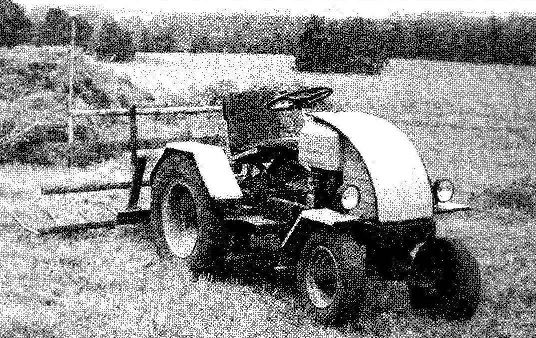
The power unit (semi-detached: engine, clutch, gear shift) with a power of 18 HP from a motorcycle “IZH-the planet” with forced air cooling of the cylinder. Fan with casing used engine motorized С3Д. For docking nodes was necessary to modify the cylinder was removed the vertical jumpers connecting the cooling fins, and the holes for the mounting studs is offset in the same circle at the angle defined “place”. On the cylinder head partially cut the fins to fit it to the size of the casing of the blower. The engine installed on the frame across. The exhaust system—a homemade silencer made from a 10-liter fire extinguisher, filling it with metal shavings. Electrical equipment, generator, switch, ignition coil — used motorcycle “Voskhod”.
Transmission uses one more (optional) gear shift—from the GAZ-51. The transmission of torque from the “planetscape” power unit for extra transmission—chain. The sprocket of the output shaft has 16 teeth and the driven—20-bevel, i.e. the gear ratio i=1,25. Chain drive is enclosed in a casing. The transaxle has a gear shaft of the PTO, which is driven mower.
Linkage for connection to tractor implements:
1 — cross member (area 75×75); 2—longeron (channel 65×36, 2); 3—jumper (area 36×36); 4—eyelet (steel sheet s4, x4); 5 —map of the hinges (the second response card is attached to the forward-mounted agricultural tool); 6—nut (from bench screw); 7—screw (from bench screw); 8—bearing; 9—additional screw terminal with welded thrust washer; 10—the lever arm; 11 —the lever handle; 12—coupling of uasin frame
Frame suspension seat on the frame:
1 — seat frame (32×32 area); 2—brace (tube Ø52,2); 3—tie (steel rod, round Ø10); 4—bracket brace to the frame (area 40×40,2); 5 —spar frame (2); 6—boot; 7—rear axle beam; 8—supporting sector of the shock absorber (steel sheet s4,2); 9—rear shock (from a motorcycle “IZH”); 10—cardan (car GAZ-66, short); 11 —front shock absorber (motorcycle “Minsk”); 12 — median reference jumper front shock absorber (the area 32×32, 2); 13—the lugs securing the rear shock absorber (area 32×32, 2 PCs.)
Rear axle of the tractor used is also from GAZ-51, it is a modified (shortened). Tires and wheels from GAZ-53 with road tread pattern and a softer cord than the regular one. In my opinion, with a little tractor (my she is a little more than 500 kg) a tire tread of a “tree” of particular advantages does not give.
The transmission of torque from the additional transmission to the rear axle is a propeller shaft, borrowed from the GAZ-66 (front, short).
Front axle used from the list … (he was back, but with guide wheels). Although he is heavy, but it didn’t have to do everything myself and besides he is”unkillable”. The front guide wheels from the car “Zaporozhets”.
Brake master cylinder and worm gear steering gear used from the GAZ-51 and other components and parts of steering control from the GAZ-53. However, the transverse thrust is made from the stretch from strollers (side of trailer) of the motorcycle “IZH-Jupiter”, and the tips she ottage “Moskvich-412”.
Due to the fact that the wheel suspension (or bridges) on the frame are rigid, the seat needed to do the suspension. It was installed on two prinovozemelsky shock absorbers, taken from the rear suspension: the rear of the motorcycle “IZH”, front—a motorcycle “Minsk”.
In the interval from the seat to the engine on the frame arranged floor made of corrugated steel sheet thickness 1,2 mm. floor mounted brackets pedals: clutch, brake, “gas”.
Before plowing on the right side of the axis between the beam rear axle and the right side member is placed intermediate piece or three pipes with a diameter of 28 mm and a length of 90 mm, connected by welded plates. Attached the spacer to the frame with long bolts. Now when plowing with the right wheel goes down in the furrow, the left above the snow, and the tractor relative to horizontal.
For connection to the tractor of agricultural implements in addition to parcopa made mounting with manual mechanical drive of the lifting and lowering implements. The drive is a vertically mounted screw gate. Screw part of it and a nut welded to the bottom of the jumper hitch used from large bench screw. Even with the right side of the frame in its Central part, welded bracket (not shown) to attach the modified and adapted the former horse mower.
On hay land tractor with trailed units delivered in the truck. It is faster and safer than their own, and not contrary to the rules of the road.
P. Kuyanov has, S. kosikha, Altai Krai
 What a strange situation in our country, anybody can afford to buy a tractor — that it is not needed (well, except for fun in a rustic Villa), and to whom the tractor is necessary, because he lives off the land — to buy it, not the means. But bare hands without mechanization on the ground not much accumulated. That forced those who no tractor can not do, to do it yourself from another suitable or remanufactured units old or abandoned equipment.


