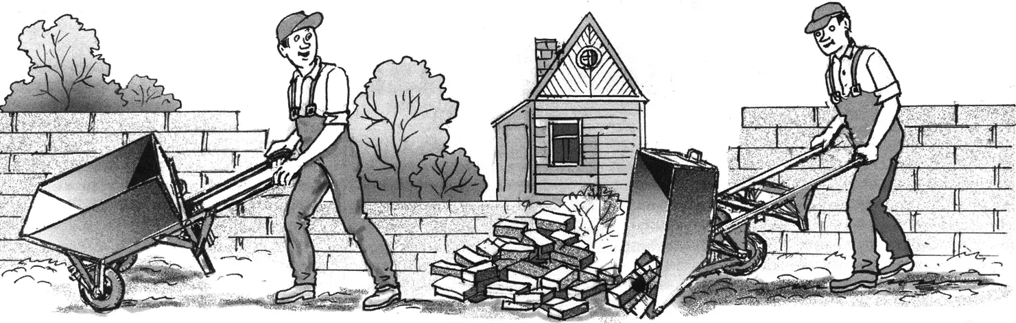
This small cart, similar in shape and size to an ordinary wheelbarrow, differs from it in that it has two wheels and a tipping body. Its other feature is as follows: the chassis is designed using metal angle bars 30×30 and 25×25 mm (previously forming the frame of an old bed).
Chassis construction
The chassis (Fig. 1) consists of longitudinal members (with handles) made of 30×30 steel angle bars 1400 mm long, connected by three cross members of 25×25 angle bars spaced 270 mm apart (with the first one set back 50 mm from the ends of the longitudinal members).
It should be noted that the longitudinal members are not parallel: the distance between them at the front is 440 mm, while between the cart handles it is 600 mm.
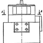
The chassis cross members can be joined to the longitudinal members, for example, with bolts and nuts. This is done as follows: 50 mm is cut off the horizontal flange of the cross-member angle bar, then the vertical flange is bent at a right angle (joint A of the connection, Fig. 1). Given the arrangement of the angle bars making up the chassis frame, the bolt holes must be made in the vertical flange of the longitudinal members.
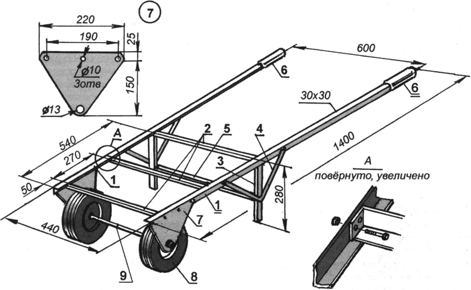
1 — longitudinal members; 2 — cross members; 3 — leg (2 pcs.); 4 — leg brace (4 pcs.); 5 — intermediate leg spacer; 6 — handles; 7 — gusset (wheel axle bracket, 2 pcs.); 8 — wheel (2 pcs.); 9 — wheel axle
The chassis is supplemented by two legs 280 mm high made of 30×30 angle bars, attached to the longitudinal members at their junction with the rear cross member. Two braces made of 30×5 strip steel connect the frame longitudinal members to the legs in a V shape at about mid-height. In addition, an intermediate spacer between the legs made of 25×25 angle bar further strengthens the structure.
Two gussets measuring 220×175 mm and 3 mm thick, made of steel sheet, are intended for mounting the wheels. They are shaped like an isosceles triangle with rounded corners. The lower holes in the gussets, 13 mm in diameter, are for the wheel axle, which is mounted not on ball bearings but on bronze bushings. The wheel axle is a steel rod 500 mm long and 12 mm in diameter (the bronze bushings must have this diameter as well, but you should also check whether it will fit the wheels you plan to attach to the cart). The axle has threads up to 80 mm long at both ends. A nut is screwed on all the way, with a washer placed tightly against it. Next the axle is inserted into the wheel bushing and the gusset hole, secured with an outer nut and washer; then an inner nut clamps the bushing against the inner surface of the gusset. Thus the bronze bushing becomes fixed, while the wheel rotates freely on it.
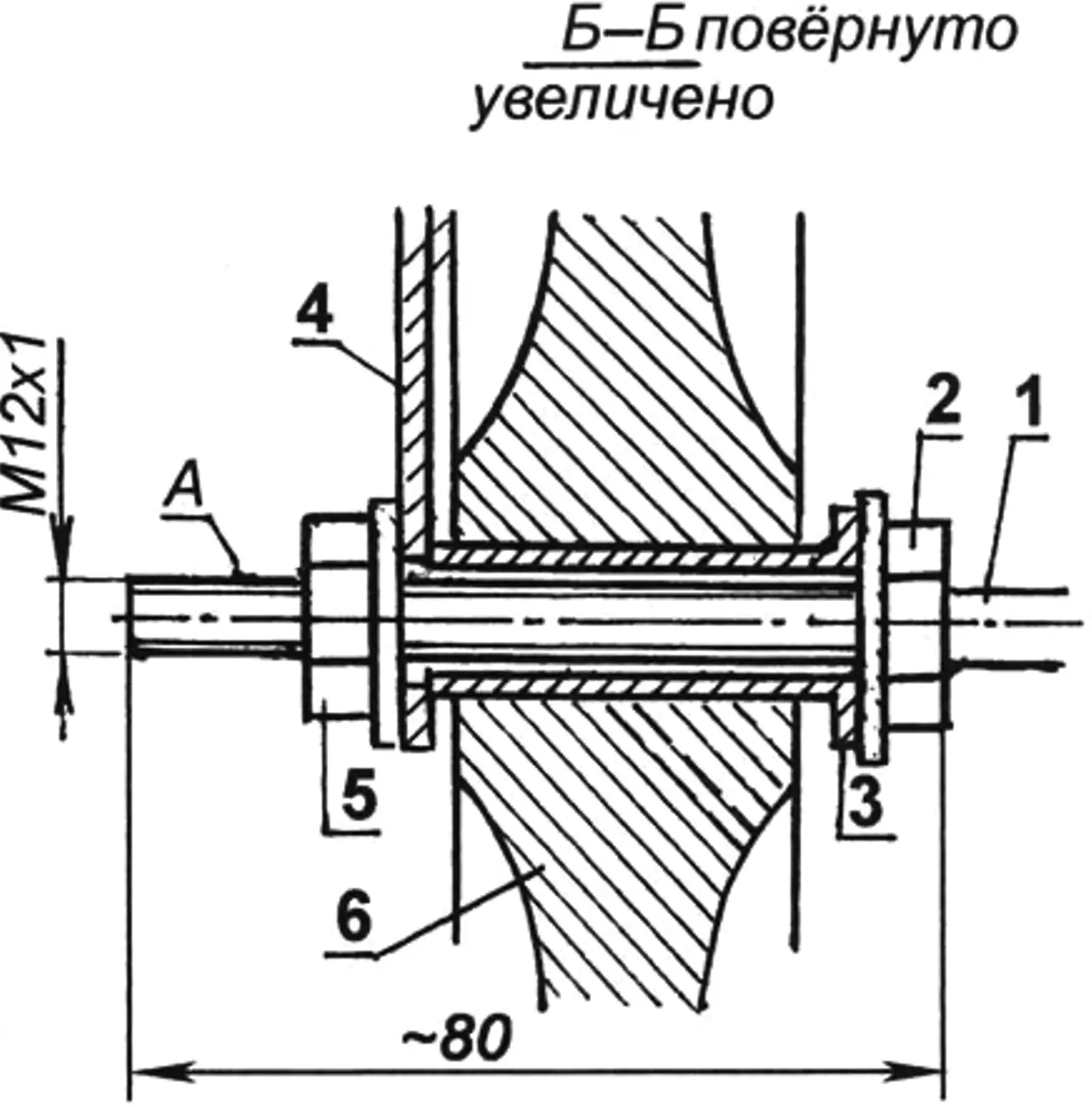
1 — axle; 2 — clamping nut (with washer); 3 — bronze bushing on threaded part of axle; 4 — gusset; 5 — locking nut (with washer); 6 — wheel.
A — threaded end of axle (for tipping brackets, 2 pcs.)
Two wheels 250 mm in diameter are taken from an old baby stroller (made of duralumin and fitted with rubber tires). After assembling the axle with wheels and gussets, the latter are attached to the frame longitudinal members. Finally, cut pieces of fabric-covered rubber hose are slipped onto the handles — and the cart’s “running gear” is ready.
Body assembly
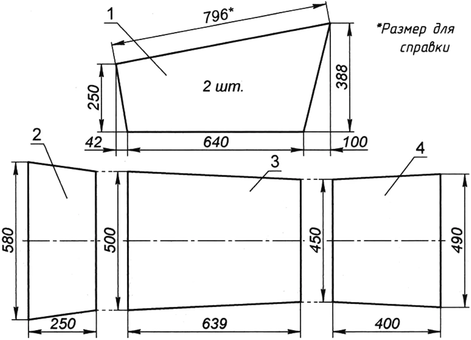
The metal body (Fig. 3) is assembled from roofing iron sheets (see Fig. 4) using 15×15 angle bars. Auxiliary frames for the bottom and end walls of the body are made from angle bars; they rest on the chassis and therefore have matching dimensions. The side sheets are attached to the corresponding angle bars of these frames with screws, rivets, or welding.
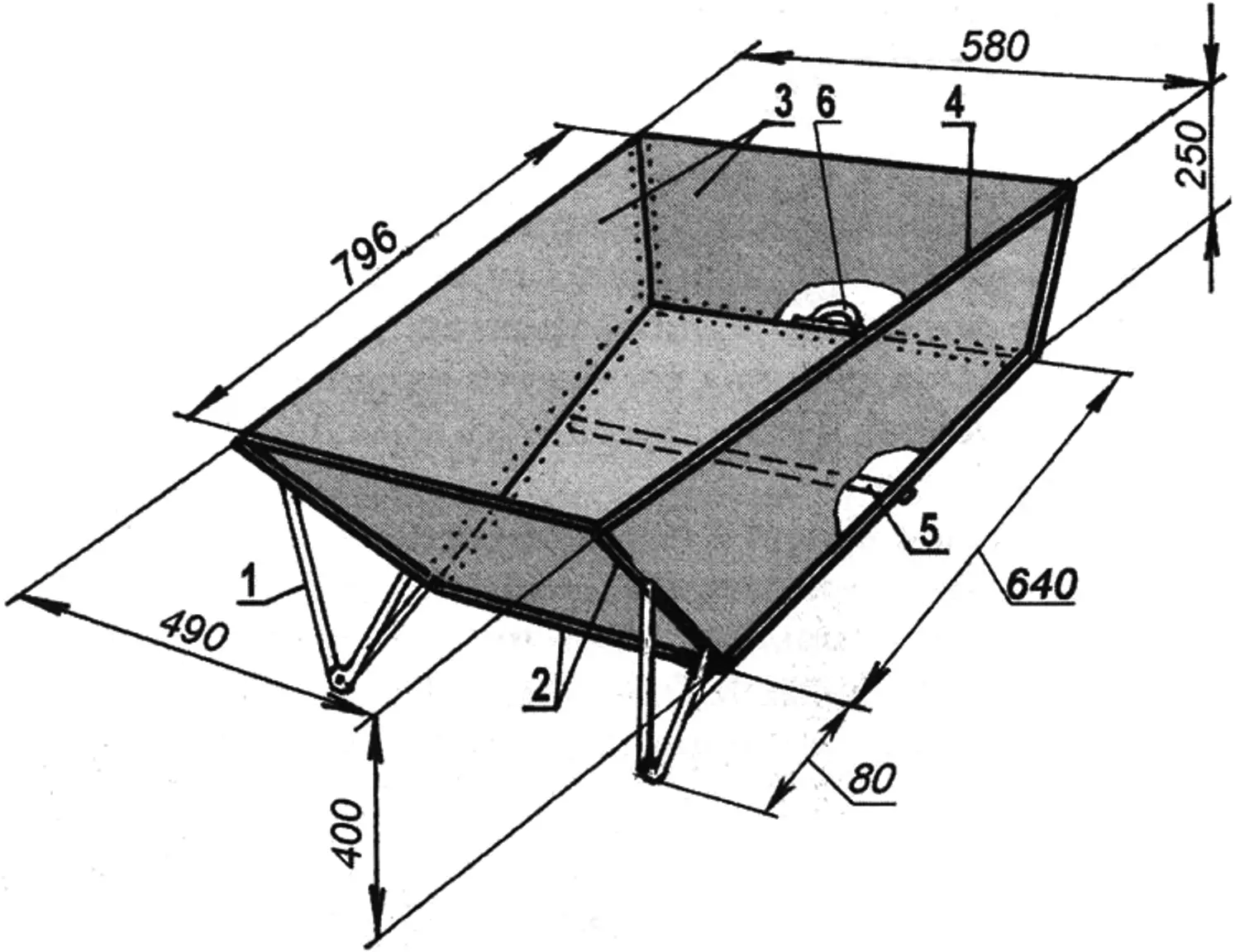
1 — body tipping brackets; 2 — frame angle bars; 3 — body cladding sheets; 4 — flanged edge; 5 — cross member; 6 — body tipping handle
Along the top of the side sheets, a 10 mm flange is bent using a hammer and pliers. This provides additional rigidity to the resulting container.
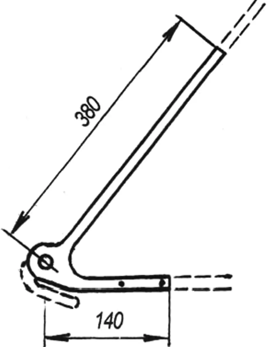
Two body tipping brackets are attached to the side angle bars of the front end wall. To make them, the rear wheel forks are cut off a frame of an old bicycle and then shortened as shown in Fig. 5. A 13 mm hole is drilled in the flattened part of the fork. The resulting brackets are then attached (with bolts or by welding) to the side angle bars of the front wall of the body (see Fig. 3). To give the brackets greater rigidity, they can be reinforced with an additional tie running from the bottom frame of the body.
1 — side panel; 2 — front end wall; 3 — bottom; 4 — rear end wall
After installing the body on the chassis, the pivot brackets remain to be connected to the wheel axle. The fork (of the pivot bracket) is slipped onto the end of the axle protruding from the gusset and secured with nuts so that it can still rotate freely when tipping the body.
To make it easier to tip the body when unloading, it is recommended to install an ordinary handle — for example, from a door or suitcase — at the midpoint of the rear bottom corner angle bar.
Using the cart
The cart can also be used without the dump body. You only need to unscrew the nuts securing the pivot brackets — and removing the body from the chassis presents no difficulty. In this way you can quickly obtain a two-wheeled barrow for various long loads that do not fit in the body.
«Modelist-Konstruktor» No. 2’2009, (Based on materials from the magazine «Système D», France)
Recommend to read
 RIGA SOUVENIRS
Great interest of young innovators, professionals of various industries has caused organized at ENEA USSR tematicheskaya exhibition "Inventors of Latvia — production". And especially the... Lean-to shelter
A Russian folk tale, “The Fox, the Hare, and the Cock,” tells us: “The fox built herself an icy hut—from snow and ice, and the hare a bast hut—from tough twigs and little...
