UNIVERSAL FOR THE FARMER

UNIVERSAL FARMER
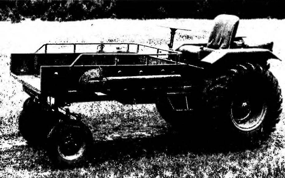
Self-propelled chassis, called the “Bull” that I built over ten years ago. For such a considerable time of operation the machine showed itself unpretentious, reliable and workable. The layout of its classic truck body front, the driver’s seat (in this case it is open) and the engine — rear; front axle — steering, rear — host. “Bull” is primarily designed for the carriage of goods weighing up to 500 kg with a speed of 35 km/h. But it is possible to work the ground. We only need, say, before plowing to replace the sprocket gearbox for a large, which will give increased traction, and attach the plow. Also, using a PTO shaft to hook up and operate a circular saw, water pump, mower, etc.

The basis self-propelled chassis frame is fairly simple outlines. It is welded from thick-walled tubes of circular and square cross-section. Numerous spot welds are reinforced with gussets and plates of steel sheet with a thickness of 4 mm with ease holes.
 
The frame is fitted with various brackets for mounting units of the power plant, transmission and auxiliary equipment. Thus, the left console frame has an angled bracket screwed to the gearbox of the winch (cable drum, it is drawn by the bolt to the jumper). Front beam carries a suspension unit of the front axle, made of steel sheet with a thickness of 25 mm and reinforced struts. The Central beam is welded to a bracket made of steel channel for mounting the steering column. Further on the longitudinal members hosted “paws” fixing the transfer case, the longitudinal arc of water pipes with corner brackets of the wings, the transverse arc with the studs of the frame of the tank and plate (u) support the rear axle. Finally, the beam is welded to the back area of the gearbox and engine mount, the cradle where their front end is still attached to a transverse arc. Above is a bracket for front mounting the engine Assembly based on the two ribs, welded to the cradle. Octagonal trim plate connects the bracket and the transverse arch.
The other end of the frame carries a motor supported by a vertical corner edge of the bar with two spacers of the square tube on which the engine rests with its rear mounting assemblies. However, the beam and rear beam are connected by two props of water pipes (in addition to its direct purpose is to provide rigidity engine mounts — struts are still spin them on a tow rope when not in use).
 
In addition, the side members of the frame installed the driver’s platform with the pedals and control levers and a cargo body. But more on that later.
 
General view of the self-propelled chassis
 
General view of the self-propelled chassis “Bull.”
 
Frame self-propelled chassis
 
Frame self-propelled chassis:
 
1 — mounting bracket reducer winch (steel, sheet s 10); 2 — hole for mounting of the winch drum; 3 — jumper (tube 60×60); 4 console (tube 60×60, 2); 5 — suspension unit of the front axle; 6,9,21 —beam front, middle and rear (tube 60×60); 7,8 — rails (tube 60×60); 10 — steering column bracket (channel 50×32); 11 — “legs” attaching transfer case (steel, sheet s 10); 12. longitudinal (tube 27, 2 items); 13 — lugs mounting wings (area 25×25, 4 pieces); 14 — bracket-engine, front -; 15 — spacer (tube 60×60, 2); 16 — bar (area 90×56); 17 — cradle engine mounts (tube 60×60); 18 — pin M10 anchoring the tank (2); 19 — transverse arc (tube 27); 20 — pad engine mounts (steel, sheet s4); 22 — front engine mounts (tube 60×60); 23 — hook towing; 24 — backup (trumpet 27, 2); 25—eyebolt М22х 1,5 (2); 26 — bottom of the reverse gear (steel sheet s10); 27 — hole under the ladder mounts on the rear axle, left; 28 — bearing rear axle, left (steel, sheet s 12); 29 — the ladder M16, left; 30 — hole M10 mounting of the driver’s platform (4 PCs.); 31 — step left; 32 — Klondike (steel, sheet s4); 33 — bracket lights.


“Bull”
 
The layout of the power plant, transmission and controls (except the pedals)
 
The layout of the power plant, transmission and controls (except the pedals):
 
1 — hoist; 2 — drum cable; 3 — the lever of inclusion of the winch; 4 — reverse lever; 5 — tank; 6 — engine; 7 — transmission chain; 8 — shaft PTO gearbox; 9 — reverse gear; 10 — rear axle; 11 — transfer propeller; 12— box transfer case; 13 — clutch Cam; 14 — support bearing; 15 — drive shaft of a winch; 16 — the lever starting the engine; 17 — the block start engine, pull rope; 18 — sprocket drive gearbox; 19 — intermediate unit; 20—the lever of a decompressor; 21 —the lever of a fuel corrector; 22 — a gear lever; 23 — lever off of the rear axle; 24 — lever transfer case; 25 — steering column; 26 — steering mechanism; 27 — fry steering; 28 — pull steering, the longitudinal.
 
Reverse gear

 
Reverse gear:
 
1 stock clutch; 2 — sliding nut; 3 — a cover of the clutch; 4 — the plug of the coupling; 5 — a plug shaped; 6 — stud M12x1,5 mounting the gearbox (4 PCs); 7 — shank shaft drive gear gearbox; 8 — nut М20х 1,5; 9 — sprocket drive gearbox; 10,14,17 — bearing cups; 11,18,19 — bearings 207; 12 — the case of reverse re-doctor (steel, sheet s8); 13 — bearings 308; 15 — flange PTO shaft; 16 — shaft flange drive gear; 20 — gear shaft drive transfer case; 21 — clutch; 22 — gear PTO shaft; 23 — ball striker; 24 — locking spring; 25 — screw adjusting.

 
The engine of the “Bull” — brand IL-P-3 (motorized FDD). Its power — 14 HP was enough. Was tempted to leave the battery ignition and electric starter. But the engine didn’t fit in the space between the wings. So I had to dismantle the bulky generator G-108 M and a starter ST-351-B. the Motor is immediately noticeable “thinner” in mass and size. Eliminated the need to relay-regulator, battery and extra wiring. Instead, I mounted generator G-421 with the contact ignition system of the motorcycle “Minsk”, which feeds the lights. The ignition coil from the motorcycle IZH-PS-350.
 
Is IZH-P-3, as has been said, Motorama welded to frame self-propelled chassis. Bracket for front mounting the engine Assembly is a box with the same tensioning device of the power circuit like on the scooter FDD. Clamps to the rear mounting of the engine and screwed the silencer.

 
Engine starts the pedal lever, a bracket which is welded to frame self-propelled chassis on the right. On the axis of the lever has a block, which is fixed to the end of a rope 5 mm in diameter. the Other end thrown over additional guide unit that is attached with a special gripper to the lever kick starter motor. After the launch of the foot lever hand lift up and fixed spring hook, that gives it fluctuate while driving.
 
To shift gears on the output roller, transmission engine is wearing quite a long tubular lever located between the driver seat and the right wing.
 
Torque from the output sprocket of the engine is transmitted to the chain sprocket drive gearbox. Thanks to the recent “Bull” has the ability to move backwards with the same velocities as forward. Gear ratio gearbox 1:1,2. He improvised, although its design used some gears and shafts of transmissions of tractors “Belarus”.
 
Case reverse gear is welded in the form of a box of five steel plates with a thickness of 8 mm. In the three side faces of the case cut the window in which is inserted the bearing cups 30 with steel shafts. Rear shaft — driven (PTO shaft), a constant gear and rotates in the same direction. The front shaft is also driven. Using a modified gimbal mechanism from the GAZ-51 it transmits the torque transfer case. The direction of rotation of the shaft can be changed by using the coupling mounted on the housing cover gearbox cover (cover is secured with eight screws M8). Thus, there are three fixed positions of the plug couplings: front — mid (neutral) back. It is controlled by the clutch lever located on the driver’s platform between the left fender and the seat.
 
Placed reverse gear between the engine and the rear axle. With the help of four studs M12x1,5 in the bottom of his case and four rubber shock absorbers it is attached to a special pad on the rear beam of the frame of the “Bull”.
 
Above it was mentioned that the plowing is necessary to replace the sprocket gearbox. Strictly speaking, the “Bull” it does not change, but Supplement it with new gear, cut from a larger sprocket (z = 42). Attaches a crown with four bolts M10x1,5. The chain in this case, of course, takes longer (and is also motorized from the FDD).
 
I agree, if someone says that this decision is not the best though, in my opinion, original. But since such a rearrangement is quite rare, to put up with it.
 
Transfer case from the GAZ — 66. The alteration was not carried out. Torque, as already mentioned, it receives from the gearbox and transmits the winch (forward) and rear axle (back). Set box on a special “legs” with a thickness of 10 mm, welded to the frame rails. Mount — four bolts М16х1,5 with rubber shock absorbers.
 
The presence of a transfer box allows bypassing the gear box of the engine, go with a reduced speed for increased and Vice versa. This ensures a gentle operation of the transmission, and hence its durability.
Driven “transfer case” with two levers placed on the driver’s platform under the seat. The first lever serves to switch off the rear axle, the other for speed selection: low or high (via neutral). Putting the lever in neutral position, you can use PTO gearbox or a winch.
 
If and to the main transmission rear axle transfer case attached short gimbal mechanism, the winch is a jaw coupling. The movable coupling half moving along the splines of the drive shaft of the winch is controlled by a lever located on the front left of the gearbox the steering column. Freewheel the winch drum has. The direction of rotation is changed by switching the reverse gear. The splined part of the drive shaft of the winch supported by a bearing, the body of which is screwed to the frame.
 
As a reducer of the winch is used a powerful worm gear mechanism of the steering column of the tractor is not known to me vintage stamps. The drum is made of a pipe, and it is wound a cable with a diameter of 10 mm and a length of 15 m. the Winch is attached to the bracket of the “Bull” with three bolts M14.
 
Steering column — from the GAZ-51. When you install it rotated around its vertical axis by 180° to the output shaft of its gearbox was on the right. The column is bolted to the bracket five bolts M10.
 
Longitudinal tie rod and some other parts of the management system — also from GAZ-51. Transverse rod and swivel arms from the FDD. Oscillating and rotary axes are lubricated through Taverniti.
 
Front axle is welded from pipes of different diameter. For greater strength of the lateral pipe (the console) are in the Central (beam) telescopically and fixed with bolts M12. To the middle of a beam welded on the edge of the power 25 mm sheet steel with spacer grommet bolt, which serves as the axis of swing of the bridge.
 
The efforts of the rotary switches is transferred to the pins via a splined joint. Because the pins turn through a limited angle, they only slide bearings in the form of a brass bushing. Directly to the pins welded to the axle of the front wheels. The wheels from the sidecar FDD. Brakes they have.
 
A way to increase the number of sprocket teeth of the reverse gear
 
A way to increase the number of sprocket teeth of the reverse gear:
 
1 — sprocket, reverse gear (z = 20); 2 — crown gear (z = 42); 3болтМ10х1,5 with nuts and washers (4 sets).
 

General view of the drive clutch gearbox
 
General view of the drive clutch gearbox.
 
Driver platform
 
Driver’s area:
 
1 — floor (corrugated steel, sheet s4); 2 — clutch; 3 — the brake pedal; 4 — throttle; 5 — brake cylinder, main; 6 — eyelet tank (2); 7 — the lever of the disconnecting rear axle; 8 — lever transfer case; 9 — the lever of the reverser; 10 — wires control in the shells; 11 — thrust adjustable; 12 — tube of the brake system; 13 — slide the pedal “gas”; 14 — spring; 15 — screw M10 mounting pads to the frame (4 PCs); 16 — steel washer; 17 — a rubber washer; 18 — rubber bushing; 19 — cushion rubber.

 
Front axle
 
Front axle:
 
1 — pull steering, longitudinal; 2 — bolt М16х1,5; 3 — arm swivel, right; 4 — Cup washer; 5 — the boot (felt); 6 — pull steering, transverse; 7 —bushing, pivot (pipe 42×32); 8 — pin: 9 — shaft; 10 — sleeve bearing (bronze, 0 32×25); 11 console (tube 50×5); 12 — bolt M12; 13 — a beam (tube 60×5); 14 — edge power; 15 — spacer (the tube 30×5,9); 16 — a bolt M18; 17 — beam frame self-propelled chassis; 18 — the suspension unit of the front axle.
 
Controls

 
Controls:
 
A — clutch B — brake; V — “gas”; G — gearbox; D — rear axle and transfer box;
 
1 — platform driver; 2 — rubber washer; 3 — the clutch pedal; 4 — brackets; 5 — spring tension; 6 — wire; 7 — emphasis cables; 8 — cover of the engine; 9 — clutch lever; 10 — the brake pedal; 11 — a brake cylinder, main; 12 — throttle; 13 — shaft; 14—slide; 15 — rod guide; 16 — compression spring; 17 —lever, kick starter; 18—the lever of transmissions; 19 — capture of a rope; 20 — unit guide; 21 — the lever starting the engine; 22 — ; 23 — lever transfer case; 24 — the lever of disconnection of rear axle; 25 — thrust adjustable.
 
Mount gas tank

 
Mount the gas tank:
 
1 — fuel tank; 2,7 — ear rubber (4 PCs); 3—frame gas tank; 4 — a holder of arc podselenie (2); 5 — bracket (2 pieces); 6 —rubber bushings (4 PCs); 8 — holder of the tank (2 PCs).
 
The position of the frame the fuel tank and podselenie on the frame self-propelled chassis (left wing is not shown)

 
The position of the frame the fuel tank and podselenie on the frame self-propelled chassis (left wing is not shown):
 
1 — plamadyala; 2 — frame gas tank; 3 — arc of podselenie; 4 — podsednik; 5 — eyelet fixing podselenie on the wing; 6 — teeth fixing podselenie; 7,8 — attachment points of the frame of the tank.


Rear axle from GAZ-51 , cropped. The length for the flanges of semiaxes now is 1220 mm. Their “stockings” the bridge is included in respective supports of the frame self-propelled chassis and dragged him to the bottom of the two ladders 16 mm diameter passing through the side members. Rear wheel from car ZIL — 157. When mounting the hubs are oriented so that the hub does not protrude beyond the dimensions of the wheels.
 
Brake system “Bull” — hydraulic, from the GAZ-51. Only acts on the rear wheels.
 
Driver platform on which the levers and the control pedals, is made of corrugated sheet steel with a thickness of 4 mm. Has two cutouts: one for the main brake cylinder and the other for “paws” fixing the transfer case. Rear brackets are installed the controls reverse-a reducer, transfer case, disconnecting the rear axle. There are welded two ears of the mounting frame of the tank. Ahead, according to the classical scheme, placed clutch pedal, brake and “gas”. Brackets pedals located under the ground. To the frame platform attached with four bolts M10 on the rubber pads.
Wings self-propelled chassis of the tractor DT-20. They had a good match in size. Yes, and many of them are relatively small. Attached wings eight bolts M10 (lugs on the longitudinal edges welded to the spars).
 
The wings have not only the role of mud flaps. They assume the mass of the rider, as they leans the seat back tube his teeth enters the nest, made of pipe cross-section of 25×20 mm. in addition, on the left wing located the fuse box and tool kit, and on the right is the air cleaner of the engine (from a motorcycle IZH-PS-350) and height adjustable arm with levers control the decompressor and fuel corrector.
 
The driver’s seat from the sidecar FDD slightly redesigned and reinforced. Can be adjusted vertically and horizontally, and recline on hinges forward, lying back on the steering wheel and giving free access to tank for refueling.
 
The fuel tank is also from FDD. Mounted under the seat on a special frame made out of pipes with a diameter of 27 mm. as the fuel tank level is below the float chamber of the carburetor, the fuel line entered Tickler pear from the boat motor “Breeze”.
 
Great attention is paid to the cleaning gas. On the label on fuel filler neck gas tank has a primary filter is a removable fine mesh. Further through the valve KP-12 filter mesh and sump gasoline for flexible rubber hoses is sequentially supplied to the transfer bag, then in the filter sump, fuel pump with its filters, and only then gets into the carb. It turned out difficult, but the operation justified it.
 
Frame fuel tank has four points of support: the bottom two (with rubber bushings) M10 bolted to the lugs of the driver’s platform, and the top two (also with rubber bushings) worn on the studs of the transverse arc of the frame self-propelled chassis.
 
The fuel tank is also recorded at four points (with rubber inserts): front — brackets welded to his frame, and the back — the same pins on the transverse arc. The abundance of rubber inserts to absorb noise and vibration generated by engine.
 
The engine is covered with a hood of sheet steel with a thickness of 1.8 mm, which is embedded behind the grille with the headlamp of a moped “Riga”. The hood opens forward and in this position is held by the backup. Closing, it falls on the two rubber cushions on the wings and “tacked on” two coil springs.
 
Ahead to the left under the body of the “Bull” has installed the headlight from the FDD, adjustable vertically and horizontally. Wiring is very simple. The control panel has a common switch and light switch “near — far” for the front lights, rear the same (remember: it was from a moped “Riga”) is only activated when reversing.
 
Truck body is welded from steel sheets with thickness of 1.8 mm and a banded area, 20×20 mm. For stiffness in the sides embossed vertical ridges, and on top put a kind of fence made of pipes with a diameter of 21 mm. Front wall hinged, fixed a hook on the end of the chain. Lowering the Board and secure it in the same plane with the bottom of the body will get an elongated platform for transportation of oversized cargo. To the left side attached bayonet spade, and to the right is the canister of fuel and a fire extinguisher. Under the body to the left and right are quite roomy, metal roof rack.
 
The body is attached in the following way. First to the frame using ladders and bolts screwed four cradle of boards and beams, pre-impregnated with hot linseed oil. And to them — the very body — the M8 bolts with round heads.
 
Take this description of the magazine, I thought that’s what. All Amateur constructors, starting the manufacture of its machines, based on the experience of predecessors. Maybe my achievements will be useful to someone.
 
V. PETROV, S. P s b n o e, Krasnoyarsk Krai

Recommend to read

  • THE LOOP – RELIABILITYTHE LOOP – RELIABILITY
    Often vladeltsy new furniture, foam manufacture of particle Board are upset - "Wipeout" from their sockets the screws fixing the hinges on the doors of cupboards and shelves. Sometimes...
  • FIRE BURNFIRE BURN
    When the firebox of the fireplace or stoves in the country wood raw material to the combustion process from time to time it is necessary to control: throw the wood, increase craving,...