“USACOM” AND HYDRAULICS

While still a student of the 3rd class of high school (20 years ago) persuaded the parents to issue an annual subscription to “modelist-Konstruktor”. Since then, and are a regular reader, cherish all the sent mail rooms favorite edition. The desire to build their own mini-tractor (MT) caught fire when in No. 12 of the journal in 1978 read the article about “Lukovichki”.

The whole year was spent on the selection of the necessary components. Back then I lived in the area, in General, non-agricultural. To get to implement his plan, anything from agricultural machinery was not possible. So in my MT most of units and parts — improvised or from written-off cars.

 
Really to create a mini-tractor was able to start only in the spring of 1988. They made it almost two summers (in winter had to do other things). But MT has propelca versatile, strong and reliable. Still nothing fails.
 
Of course, the tractor would be the engine of the motorcycle “Ural” and “Dnepr”. But there I was not. Had to settle for “usacom” PD-10U, replacing his regular cylinder for a more powerful (from a motorcycle “IZH-the planet”) according to the method which repeatedly and in detail told the journal “modelist-Konstruktor”. I consider it necessary only to add: when modifying the engine it is desirable M10 studs of the cylinder to take a little longer than usual, instead of carb K-28 set of high-performance K-62 with a homemade straight pipe, eliminating the leakage of gasoline through vostokfilm and the cooling cylinder to improve by the fan D-37, equipping it with a casing for the directional air movement.
Drivetrain the mini-tractor is based on the classical sequential scheme with the driven rear axle. Engine PD-10U directly link located at the bottom of the frame level with the regular grip, and it, in turn, with a homemade reducer. The torque is transmitted from the last node of the power (in the kinematic scheme conditionally missing) and the box changes gear (transmission) from the GAZ-51. And made it so that a United body bolts are “monolithic” power unit.
 
Kinematic diagram of the transmission (unit power take-off conventionally not shown)
 
Kinematic diagram of the transmission (unit power take-off conventionally not shown):
 
1 —engine PD-10U (modified) clutch; 2 — wheel front (from the car “Volga” GAZ-21); 3 — reducer homemade; 4 — gear shift (from car GAZ-51); 5 – transmission of the prop (from the GAZ-66, short); 6 — transmission main (the rear axle of the truck ZIL-157, cropped); 7— rear wheel (ZIL-157).
 
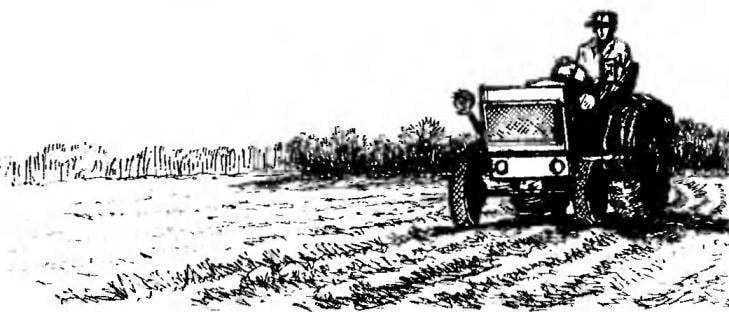
Mnnn-tractor (General view)

 
Mnnn-tractor (General view):
 
1 — headlight (2); 2 — hood; 3 — engine; 4 — fuel tank; 5 — mirror; 6 — main light switch; 7 — wheel steering; 8 — control hydraulics; 9 — the driver’s seat; 10 — hydraulic hoses; 11—hydraulic cylinder; 12 — hitopadesa; 13 — rear wheel; 14 — malereproduction two-piece; 15 — a hose plum of oil; 16 frame; 17 — steering gear; 18 — wheel front; 19 — beam front axle; 20 — oil tank; 21 —the lever of switching gear; 22 a clutch lever; 23 — wing; 24 — rail; 25 — tool box; 26 — splash shield; tow 27; 28 — pull steering, longitudinal; 29 — pull steering, transverse.
 
Power unit (reducer removed)

 
The power unit (reducer removed):
 
1 — engine PD-10U; 2 — a pulley presenter (odoroki-with left) of the host PTO; 3 — clutch; 4 — spring; 5 — hinge Assembly PTO, mounting; 6 — gearbox; 7 — beam of the frame of MT; 8 — spar angle; 9 — an arm (with two ball bearings and driven shaft) of the host PTO; 10 — tension pulley 11 —belt A700; 12 — pulley driven (obnarujeny) node power take-off; 13 — a pulley dvuhruchevaja.


Frame system gidroponiki similar to those that were published in the “Modeller-designer” № 10’5 85 and’94. It is based on a welded rectangle 2170×650 mm. Material — steel channel No. 18 taken with a substantial margin of safety to during the operation do not be afraid of distortions. Taken into account that the frame has multiple cutouts (under PTO and the stepladder under the rear of the bridge) that require structural reinforcement.
 
At the beginning of the frame bottom to fasten the brackets on the front axle and the rubber bump stops and the rear part of the bolt-M10 —front of the channel number 12 for installation of the hydraulic cylinder and the two plates connecting the pendulum suspension with welded tow bar.
The hydraulic device of the tractor is also unsophisticated. It does not differ from the technical decision, which was published in the above journal. The hydraulic cylinder lowers-raises and holds at the desired height of the suspension frame, welded from steel unequal angle so that the cross section of each power element was a square.
 
Front axle is a beam — a thick-walled pipe welded to its ends pivot bushings from segments of the same pipe. In the middle of the beam is welded to the bearing housing axis of oscillation of the bridge, reinforced with steel gussets.
 
The rotary axle of the wheels cut from channel number 20. To the shelves of the holes and tapped M8.
 
The thickness of the ring flange are not the same. It is made for camber of the front wheels.
 
Generator-node vatnshorn
 
Generator-vatnshorn site:
 
1 — the bracket is welded (steel area 40×40); 2 fan D-37 air-cooled engine; 3 — strap А630 (2); 4 — pulley dvuhruchevaja; 5 — alternator.
 
Node power

 
Host power:
 
1 —– the double-pulley; 2 — a pulley driven; 3 — bracket output shaft; 4 — spar angled; 5 — loop fasteners.
 
Frame bag FR-tractor hitopadesha


Frame bag FR-tractor hitopadesha:
 
1 — base (steel channel No. 18); 2 — cross bar (angle steel 50×50, 4 pieces); 3 — bracket front axle (steel plate 200x170x10, 2); 4 — rear axle bracket (steel plate section 180×10, 2); 5 — bracket (steel strip section 150×10,2); 6 — bracket strengthening (steel channel No. 12, L70); 7 — (steel channel No. 12,L450); 8 — suspension frame (angle steel 40×40); 9 — bushing (steel pipe 60×10, L80, 2); 10 — cylinder; 11 — turnbuckle (steel plate 120х80х 10 with hole Ø 40); 12 ’ scarf (steel plate 70x70x10,2); 13 — absorber-limits-tel of rotation of the front axle (2 PCs.)
 
 
Front axle
 
Front axle:
 
1 — axle beam (steel pipe 57×8, L975); 2 — insert axial bearing (bronze, 2pcs); 3 — housing of the axial bearing (steel pipe 50×5, L190); 4 — gusset plate (a steel plate 100x20x5, 4 pieces); 5 — rotation limiter (steel hexagon bar, h50, 2); 6 — bushing, pivot (steel pipe 57×8, L110,2); 7 — liner (bronze, 4 items); 8 — washer oblique (ST5, 4 PCs.); 9 — pin (bolt M20-2 PCs); 10 — axle swivel (steel channel No. 20, L145, 2); 11 —flange ring (from the UAZ-452Д, upgraded, 2); 12 — cosina (45x45x10 steel plate, 2 PCs.).
 
Modernized fly steering of UAZ-452

 
Flew upgraded steering gear UAZ-452:
 
and connection steering bipod with the left axle;
1 — fry steering (2); 2 — thrust of the cross; 3 — pull longitudinal.


Steering model. Swivel bipod homemade. Welded to the axles, they have the sleeve with a conical hole for a finger pull. Lever for rod — factory. Axle with axle beam connected by pins.
 
Rods — UAZ-452: control, cropped (by bending) to the length of 950 mm, and longitudinal — up to 600 mm. From the UAZ-452 is taken and the power steering gear. But as its body is a steel mount, borrowed node had to be installed vertically, welded to it cut a steel angle 70×70 mm and through it to attach to the frame of MT bolts M8.
 
Steering shaft (UAZ-452) I redid it, extending through warney bushings were 20 almost 150 mm and setting it on the lower end of the propeller plug steering from GAZ-66. For this sawed hollow steering shaft in two, drove in each half of a segment of steel rod with a diameter of 8 mm, leaving a free end length less than 10 mm, and insert them on both sides in the hub clamped in the vise, welded together.
 
With the steering column I did differently: instead of too short “Wazowski” installed on my mini-tractor homemade, cut from gazotoplivnoy pipe of suitable size, which is bored through on a lathe socket under the steering shaft bearings. The results were satisfied.
 
A. KLIMENKO, Primorsky Krai

Recommend to read

  • “THIRD HAND” TWEEZERS“THIRD HAND” TWEEZERS
    Hams know how sometimes when soldering they do not have a third hand to fix a small detail. At the time it was proposed many devices that can help in such a situation (see, for example,...
  • THE SUSTAINABLE DIPLOMATTHE SUSTAINABLE DIPLOMAT
    All good hard portfolio of type "diplomat", but he has one disadvantage — poor resistance. It falls down when it is put on carelessly. Rescue a kind of rotating "legs" is attached to the...