Walk-behind wheel:
1 — handle throttle control and clutch (scooter Elektron), 2 — rod control (from the segment of the tube 21,3×2,5 steel vodova-zapovednoj, 2), 3 — longeron H-shaped frame (cut from milled steel channel steel, 2 PCs.), 4 — shift speed, 5 — plow horse with stepped height adjustment-direction, 6 — crossbar of H-frame (welded construction of segments 6 mm of STZ plate and a steel angle 45×45 mm) 7 — gas tank (from 0.5 to 1 mm galvanized sheet), 8 — star, Z5=24 (fixed on the intermediate shaft prismatic dowel and nut M16 washer grower), 9 — pull speed switch ( segment “wire rod” 0 5 mm), 10 — the case of drum type (from 2.5 mm aluminium sheet size 260х 1650 mm, rolled into a ring, and riveted the ends of curved ribs — STZ 2.5 mm thick), 11 — power unit (motor scooter “Electron”) with forced air cooling, 12 — adapter for the kick starter (St1), the 13 — lever kickstarter, 14 — silencer 15 — bracket-clip (of 5 mm STZ), 16 — clip (bronze, brass, etc., 4 PCs.), 17 — roller axis (45 Steel, 4 PCs.), 18 — air cleaner (from 0.5 to 1 mm galvanized sheet), 19 — wheel rim (from a 2.5 mm sheet of STZ), 20 — protector (from old tires with sidewalls remote from the vehicle ZIL-130), 21 — disc-bracket transitional (intermediate) shaft (welded construction of 3 mm STZ and cut pipe 100×3 steel vedovato-wire), 22 — ring adapter (STZ; binds the asterisk Z4=40 and the disc wheel with the outer ring of the bearing 80220), 23 – 80220 bearing with shields, a 24 — second stage chain transmission Z3=13, Z4=40 (and PR — 12,7), 25 — shaft intermediate transition (Steel 45), 26 — the first stage of the chain (Z1=10, Z2=30 and PR — 12,7), 27 — mounting plate (STZ), 28 — bolt-bracket (welded structure with bolt M16 and 124 mm cut strips STZ 10×30 mm cross-section), 29 — bracket “Crescent” (from STZ welded to the inner ring of the ball bearing 80220), 30 — disc drive wheel (3-mm STZ).
The earthen mill.
Lever Assembly-shifter.
Left to the body, attach the drive sprocket Z=40 motor-plow. To this end, the end of the cylinder drilled 12 holes and cut thread M8. The ribs on the right side have notched form. The cutouts serve for the exit pipe of the muffler and install the kick starter lever. Around the circumference of the housing (on the right side during the motor-plow) cut 4 rectangular Windows 20×50 mm for mounting supporting rollers with the axes. The rollers can be made of any material — bronze, brass, steel…
Inside the case is not the only engine with intermediate shaft, but benzobak. And — with the air cleaner. When pouring fuel, Unscrew the “wing” (at the top), take out the tank. And after filling — put everything back in place and tighten the “wing”.
Air purifier inside the Packed filter material. Provided a cavity for pouring oil. To the body of this node is attached with eyelets and bolts MB. And with the carb connects to a rubber hose (of the scooter).
Drive-intermediate shaft bracket is made of 3 mm sheet St3. The detail of this cut with one hand. In the disk there are two groove (width of 75 mm and 45 mm) and 94-mm hole in the center. And on a circle with a diameter of 460 mm drilled twelve of 8.2 mm. This also is welded and the hub axle of 38 mm pipe cut 100×3. On it is mounted a ball bearing with an inner ring diameter of 100 mm (e.g., from caterpillar tractor).
Sprocket Z=40 first rassverlivajut in the center, and then chiseled the outside diameter of the bearing. Then according to the diameter 205 mm perform six holes M8.
To the star n the bearing tightly to the weld, and to easily replace it (just in case), had to make a special ring (see Fig.), at 205 mm in diameter 12 holes. Six of them with a diameter of 8.2 mm are used to mount the rings with an asterisk. Same, but with thread M8 for durable connection with the drive wheel. The latter is pre-installed on the bearing with the subsequent welding thereto (“sticking”). Then to the inner ring of the bearing bracket and welded the half moon. He will serve for the fastening of the whole structure of the motor-block to the left longitudinal member.
After half moon and the ring will take its place (they are welded with one end face of the bearing), I start assembling the whole site. In particular, the bearing is mounted sprocket. It is attached to the ring bolts. Moreover, between the ring and laid with a star washer. Then bearing along with a star and a ring set per cylinder (see above), welded to the disk. Of course, this is best done using pressing. But (at least) you can “grab” and welded.
The wheel disk is made of 3 mm St3. Diameter 590 mm there are 12 mounting holes n rim, which is bent from a sheet St3: it is a cylinder, the ends of which there are ribs with twelve holes around the circumference Ø 590 mm. From the back of the collar (opposite the holes) welded M8 nut.
Why is there such complexity? And because the ribs serve not only to mount the rim to the wheel disc, but also act as stiffening ribs. In addition, they function as a kind of guide. For the protector, of course. To “not fly” with the rim.
The protector is cut from old tires (from cars ZIL-130). And used the latter only the upper part of the sidewall removed. This kind of harvesting itself and the wheel rim with the subsequent retraction of the clamp from a wire of 6 mm.
Once the wheel is ready, a chisel or a chisel to deepen the existing lugs, with their “tree” (for example, the tractor “Belarus”). You can go, as they say, even further. To avoid slip during ploughing positioned on the circumference of the wheel lugs extra, strengthening them to the rim (to nuts on the ribs).
The design of the cultivator is such that on the sides it has the power spars (made from lengths of steel channel), the edges of which are milled to a thickness of 1 2 mm. the Right is mounted with a curved bracket-bracket, bolted to the hull with four bolts M8. Here is the right bearing housing intermediate shaft. And the left side rail with the same bolts pressed to the plate with special mounting bolt bracket. Moreover, this bolt is screwed into the “Crescent” and serves to create additional convenience during Assembly.
To increase the rigidity of attachment of the spars, and installation of the plow and other implements is provided located immediately behind wheel cross member. It is welded from pieces of steel angle with holes Ø 8.5 mm (every 30 mm). Latest serve to a quick reshuffle of the plow, change the width of plowing in one pass.
Adjusting-holes (but Ø 8.2 mm) are on all the spars (for their entire length, every 40 mm) for changing the distance from wheel to wheel. The last taken of the scooter “Electron”. As for the brackets helm, they are made of water-gas supply pipes 21,3×16,3.
The intermediate shaft is mounted on two bearings with an inner diameter of 20 mm. But can be used here and the bearings 205*. However, this will require minor changes in the diameter of the shaft. The bearings are installed in housings from St3, with 3 holes of M8. Moreover, the, which is located on the right side, mounted to the curved bracket and the edge of the hull with bolts M8. Stand right side of the intermediate shaft is mounted sprocket Z=24 — to drive the excavation tool.
And a few comments. As practice shows, when you install the motor immediately, must be clearly regulated. The reason is clear: because then access to it is somewhat complicated. As for the muffler, it is better to take from some (including old) scooter. But you can make yourself (see picture). from a sheet of galvanized iron with a thickness of 0.5—1 mm.
The plow is also desirable to use a horse, without any alterations. But the earthen mill homemade. Consists of a rotor on which are mounted the legs. Length: 225 mm — “large” and 190 mm is “small”. The rotor is rigidly fixed on the axis. And the last one on the bearings. Shells were “planted” on the cutter body, which is also the casing, preventing the spreading ground the ground up and in the direction of the ploughman. The housing is attached to the cross member hinged to the cutter can be raised (lowered), thus regulating the depth of cultivation.
The rotor can be made of cut steel pipe. 195×3, to which are welded the blades 40 mm wide and 4 mm thick each. Just design 20 knives.
Finally, the last. The ratio of teeth of the sprockets on the intermediate shaft such that the rotational speed of the auger must be greater than the speed of rotation of the drive wheel.
A. ZOTOV, Cheboksary
Recommend to read IN WINTER — SNOWMOBILE, IN SUMMER — AIR SUSPENSION Such a transformation that my construction readily admits. Moreover, the possibility of replacement ski floats, making it easy to turn a land car in "waterfowl". Flat "breaking" the... CONVENIENT SCREWDRIVER The usual tip is a spatula she is hidden by a rubber tube. This sheath not only protects the working tip of a screwdriver, but pockets. Pulled the head of the screw, it will screw it in... 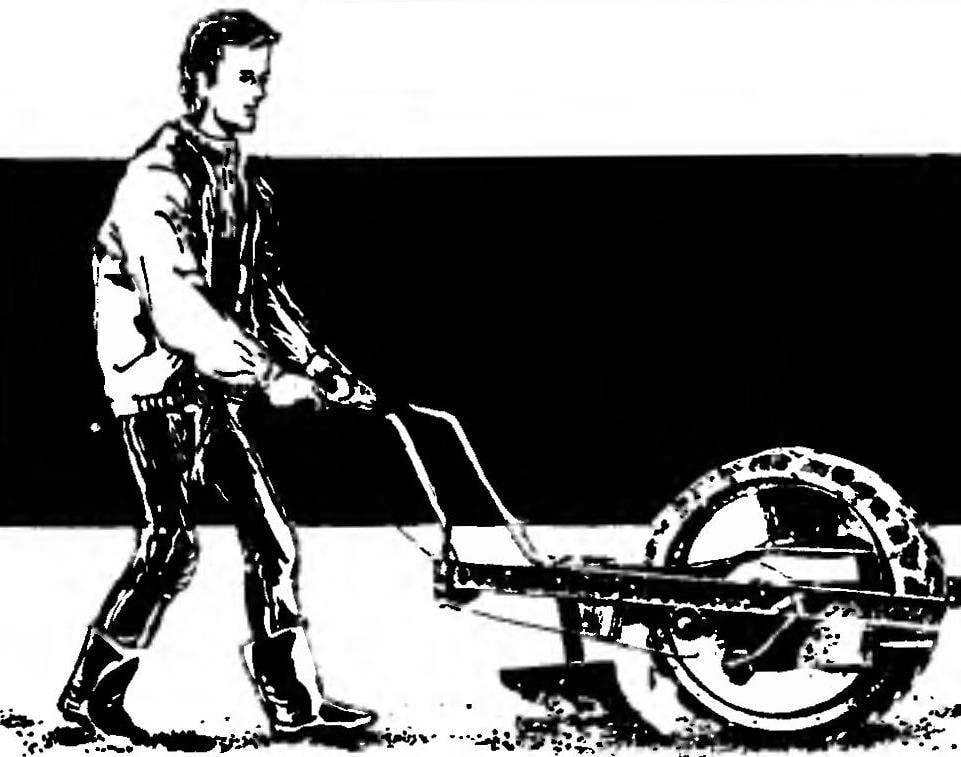
 The proposed development is suitable for plowing the infield with a small plow, loosening the soil using the excavation tool. In addition, this cultivator can perform the planting and ridging of potatoes.”The heart of the” mechanical assistant (power plant) the engine of the scooter Elektron with forced air cooling and handles the throttle and clutch (with cables taken from the same scooter). The drive sprocket of the engine is also “a regular”. Gear changes can be left motorolleri, rope. But it is more convenient to bring it directly to the spar tillers. The programs will switch with levers and rods.