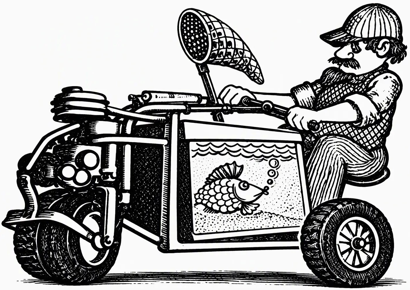
In one of the episodes of the Central Television program “You Can Do It” (“Eto vy mozhete”), viewers met the amateur designer Oleg Andreevich Ostapenko. We have already grown used to the fact that “EVM” introduces us to people whose technical creativity invariably arouses interest and surprises us with unexpected solutions to various design problems. But even they, as a rule, demonstrate no more than one or two developments. Ostapenko, however, did not merely surprise us — he astonished us with the breadth of his interests. He is the author of two original mini-tows, an amphibious all-terrain vehicle, a “forest” motorcycle, and even a disc-shaped aircraft. In our “Photo Panorama” (see “M-K” No. 1, 1986) we briefly described the successes of this remarkable man in technical creativity. Today we invite readers to become acquainted with the description and drawings of one of O. Ostapenko’s most popular designs — the mini-tow.
Walk-behind tractors are usually built with the desire to ease labor primarily in the garden. Hence the design solutions that take into account aggregation with various plows, cultivators, harrows, and other soil-working implements.
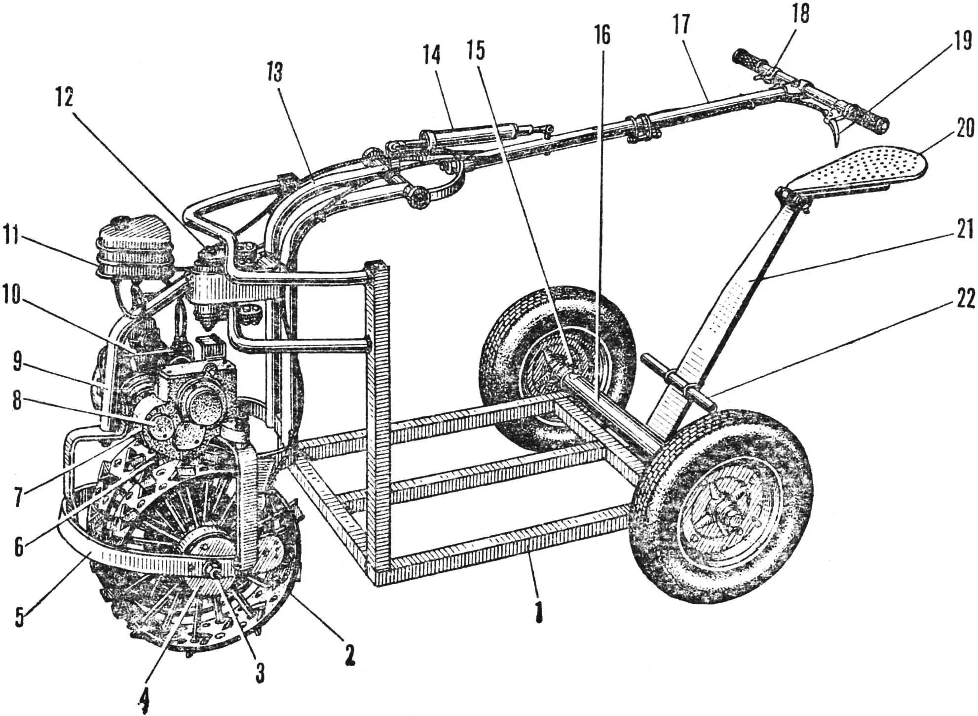
1 — cart, 2 — wheel unit, 3 — unit axle, 4 — brake drum, 5 — tow frame, 6 — chain, 7 — gearbox, 8 — power take-off shaft cover, 9 — pivot-unit arch, 10 — engine, 11 — fuel tank, 12 — pivot-unit axle-stud, 13 — pivot unit, 14 — shock absorber, 15 — wheel-tube mounting bolt, 16 — wheel tube, 17 — steering bar, 18 — throttle lever, 19 — brake lever, 20 — seat, 21 — leaf spring, 22 — footrest.
I, however, conceived my walk-behind tractor for mechanizing work related to moving loads over short distances and on terrain with many slopes. I will not say that it looks unusual. Amateur designers widely use the walk-behind tractor–cart combination. Yet there are special features in my machine. I would like to tell about them.
My walk-behind tractor is a compact two-wheeled tow, hinged to a cargo platform. It is controlled by means of a steering bar, which the driver holds while walking or sitting on a sprung seat.
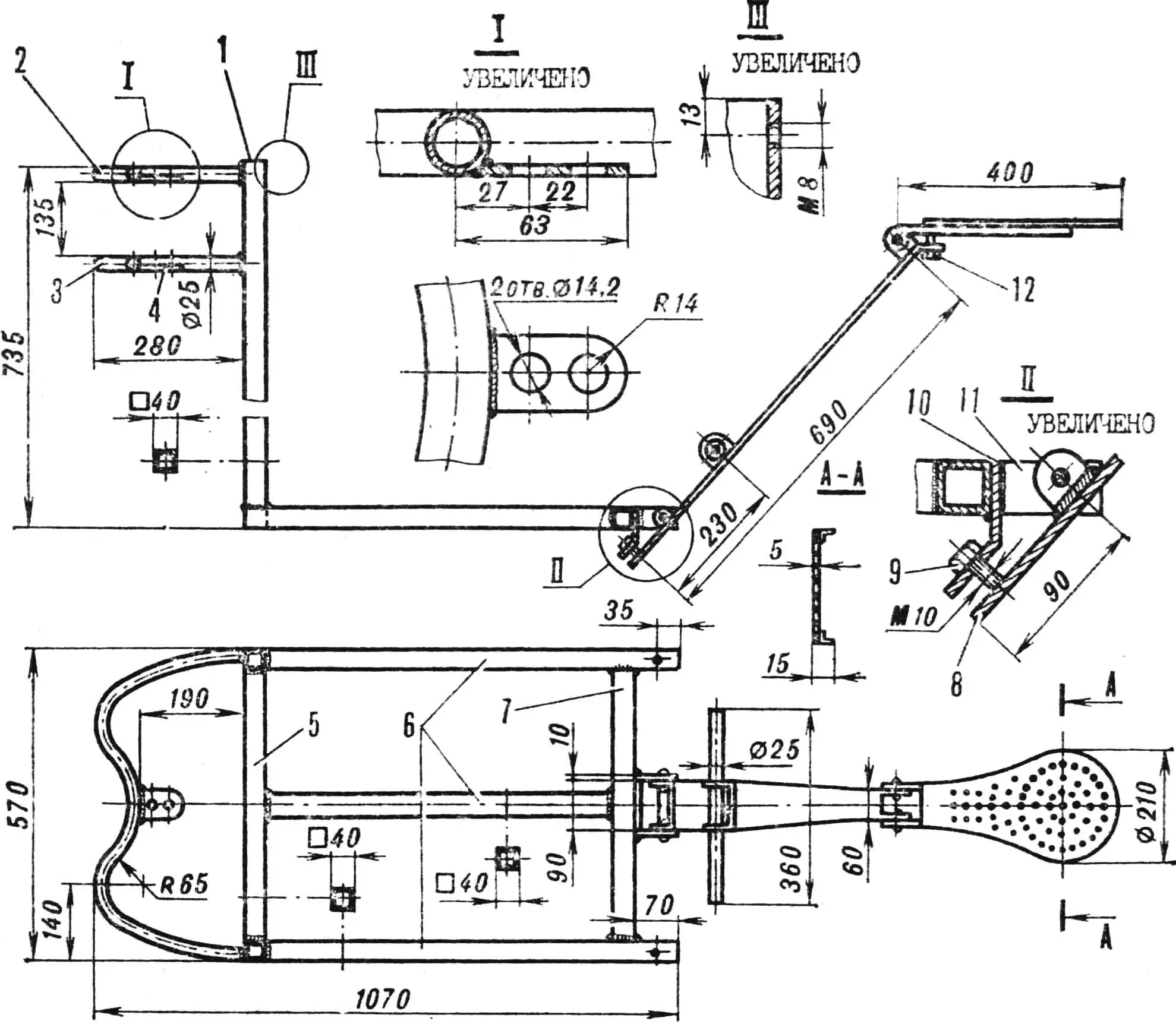
1 — upright, 2, 3 — shaped tubes, 4 — bracket, 5 — front crossmember, 6 — side members, 7 — rear crossmember, 8 — leaf spring, 9, 12 — seat-height adjustment stop bolts, 10 — clamp, 11 — side-member end piece.
The tow design is simple and subordinated to the tasks it performs. The main one is to pull the cart (platform). Therefore the wheels (from a motor scooter) are locked together — their disks are rigidly joined by four bolts. Two massive washers are clamped between the disks: they are intended to increase the tow’s weight, which improves the grip of its wheels with the soil. In the left washer, welded to the unit hub, a groove is made — a ring is seated there that carries two important elements of the tow design: a winch drum with a steel cable Ø 5 mm and about 50 m long, and a driven sprocket (45 teeth) riveted with twelve pin-rivets. The ring rotates freely on the washer — in this case the running gear is disconnected from the engine, and the walk-behind tractor can be moved by pushing it, for example, up to a load. But as soon as you turn the handle inside the right-hand wheel in the direction of travel (shown on the left in the drawing), the spring-loaded locking rod enters a hole in the ring and locks the wheels to the engine.
A scooter brake drum is welded to the left disk.
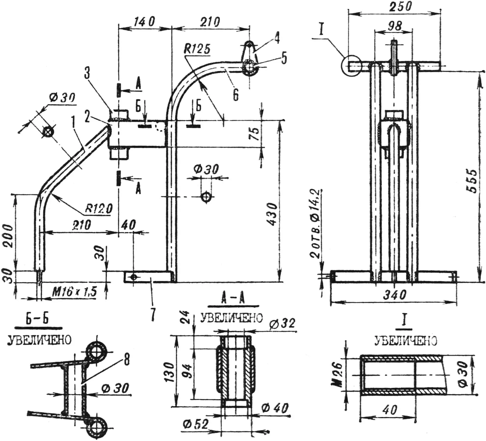
1 — arch, 2 — pivot-bushing bracket, 3 — pivot bushing, 4 — rocker, 5 — steering-bar cross tube, 6 — pivot-unit tube, 7 — clamp, 8 — spacer.
The winch is intended for negotiating steep climbs when wheel grip on the ground is insufficient. The cable is unwound, taken to the place where the load must be delivered, and hooked to a tree. Rotating together with the wheels, the drum winds the cable, and the walk-behind tractor pulls itself up the slope.
Another means of improving the tow’s traction characteristics is also provided — a unit of metal wheels with angle-iron lugs (they are clearly visible in Figure 1). Its design uses the same washers, hub, ring, and sprocket (but without a winch).
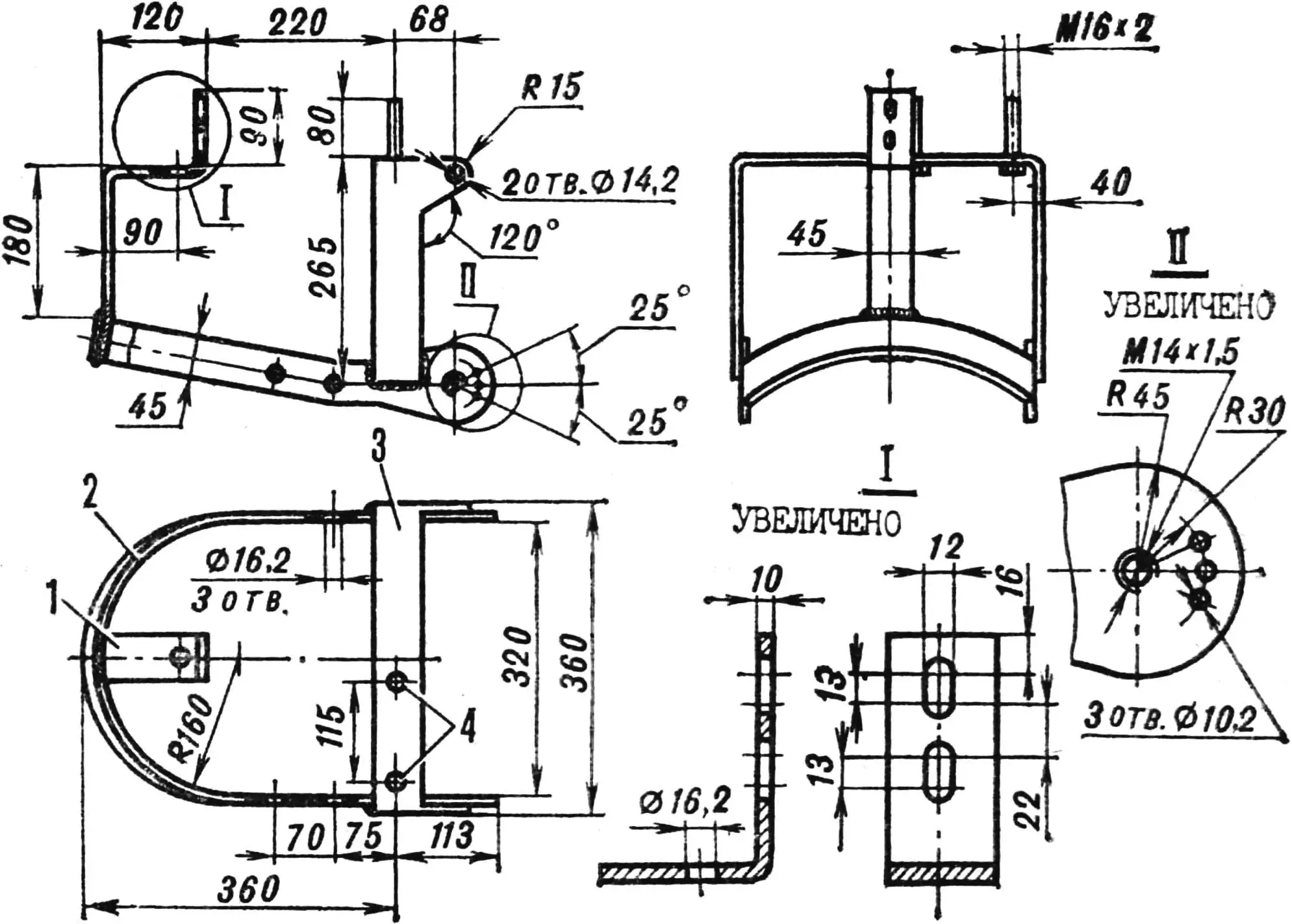
1 — front bracket, 2 — belt, 3 — U-shaped crossbar, 4 — M16×2 bolts.
A compact Druzhba-4 chainsaw engine of 4 hp is used as the power unit. It has an automatic centrifugal clutch that engages when the crankshaft speed increases.
The engine is connected to the housing of a reduction gearbox (1 : 16). The gearbox crankcase is sealed with oil seals, filled with hypoid oil, and fitted with a flange (at the input shaft) similar to the flange for attaching the engine to the chainsaw.
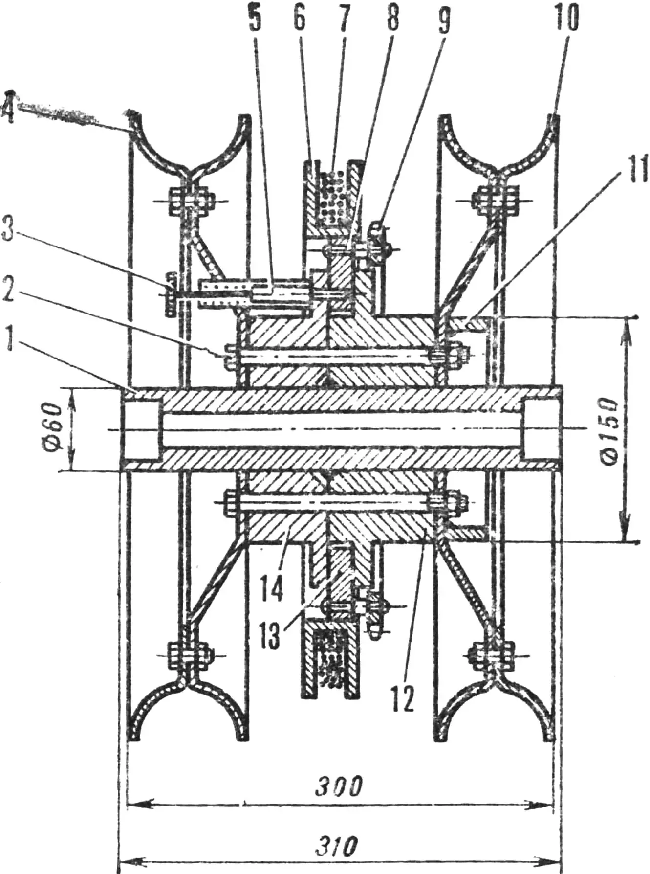
1 — hub, 2 — M10×1.25 bolt (4 pcs), 3 — lock handle, 4, 10 — wheel disks, 5 — lock rod, 6 — winch drum, 7 — cable, 8 — pin-rivet, 9 — driven sprocket, 11 — brake drum, 12, 14 — washers, 13 — ring.
The gearbox is attached to the tow frame at three points: to the U-shaped crossbar and the front bracket. Its output sprocket is located above the driven sprocket of the wheel unit and is connected to it by a chain.
From the opposite end of the gearbox input shaft, closed by a removable cover, power can be taken off to drive a mower, a circular saw, or a pump — for pumping water into a transportable tank of 250 L capacity.
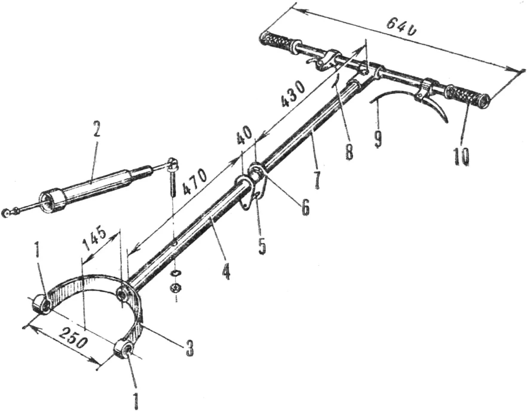
1 — bearings No. 201, 2 — shock absorber, 3 — yoke, 4 — bar, 5 — bar-length adjustment screw, 6 — clamping nut, 7 — rod, 8 — throttle-lever cable, 9 — brake-lever cable, 10 — handle.
The tank is riveted from aluminum sheets and angles, sealed, and fitted with a hinged lid. It is fastened to the cart with four bolts: two on the frame uprights and two on the wheel tube. The tank is mounted at an angle so that the front wall forms a closed load-bearing triangle with the uprights and side members, since there are no other special elements reinforcing the frame.
The cart frame is welded from rectangular-section tubes. At the rear, the wheel tube is attached to the side-member end pieces, and to the rear crossmember, on a special bracket, a 10 mm thick steel strip with the driver’s seat, footrests, and seat-height adjustment stop bolts is mounted.
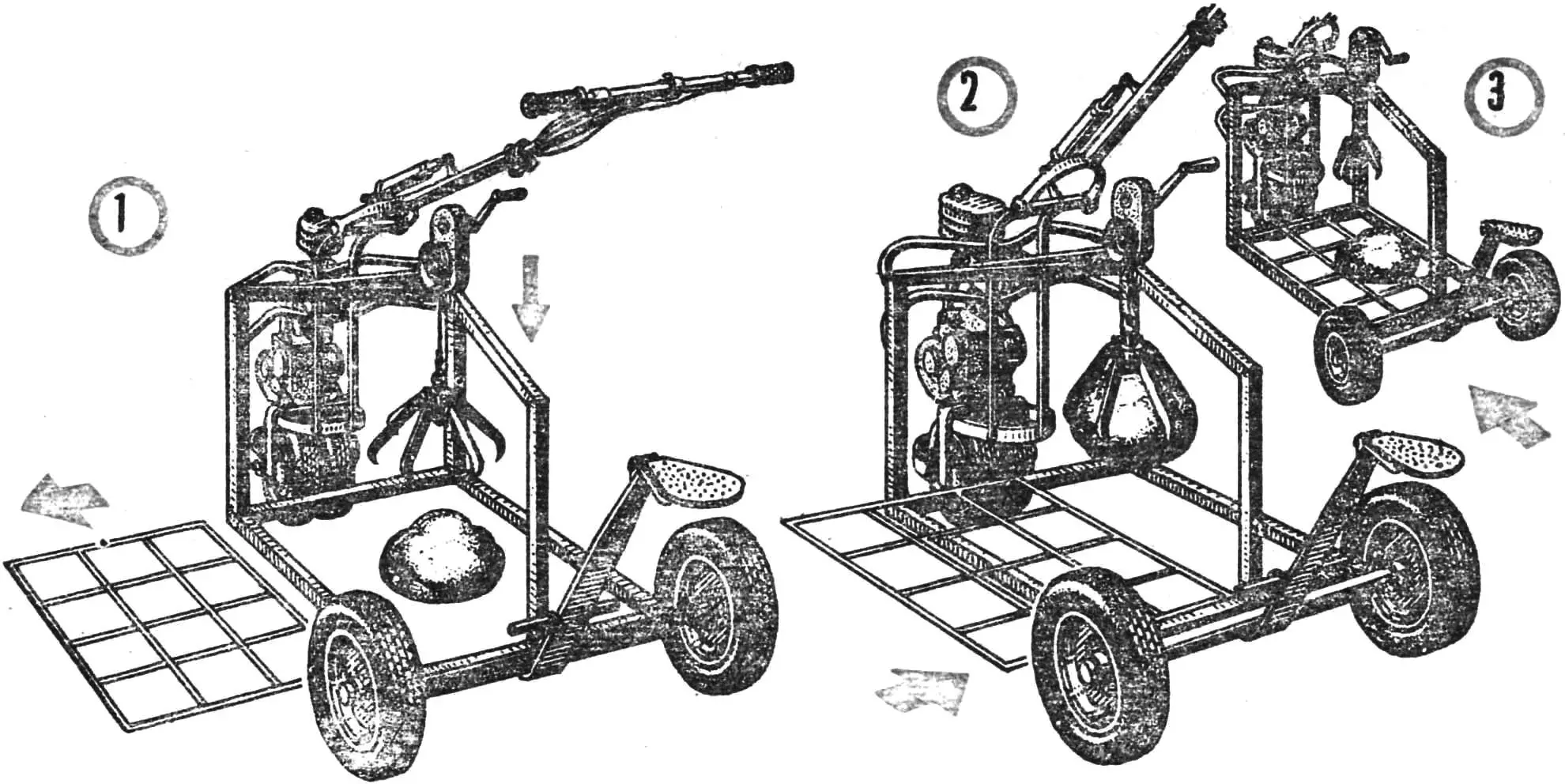
1, 2, 3 — sequence of operations.
At the front, two shaped bent tubes Ø 25 mm with brackets for attaching the tow’s pivot unit are welded to the uprights parallel to each other.
The pivot unit is a structure welded from tubes and strip elements. It is attached to the tow frame at three points: to the U-shaped crossbar and the front bracket.
The pivot bushing is among the most heavily loaded parts. It is connected to the unit tubes by a wide steel strip and carries two ball bearings: in the upper seat — an angular-contact bearing (No. 446203), in the lower — a radial bearing (No. 203). An axle-stud with a shoulder for resting on the inner race of the angular-contact bearing is inserted into them. By two horizontal shackles the axle-stud is connected to the brackets of the cart’s bent tubes.
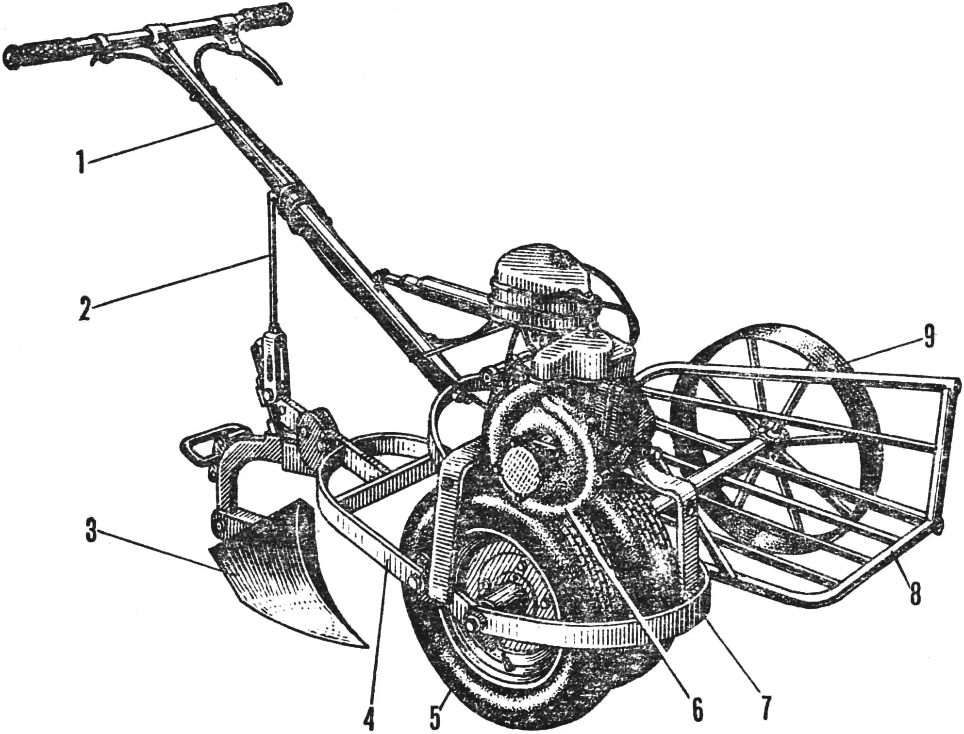
1 — steering bar, 2 — additional stop, 3 — plow, 4 — plow carrier, 5 — wheel unit, 6 — engine, 7 — tow frame, 8 — luggage rack, 9 — luggage-rack wheel.
The pivot-unit tubes end with a clamp for attachment to the tow frame (at the bottom) and a steering-bar cross tube (at the top). The ends of the cross tube are threaded, and a rocker for the steering-bar spring shock-absorber rod is welded to its middle. The latter is intended for controlling the walk-behind tractor and is equipped with all the necessary levers and mechanisms. It is suspended from the cross tube by a yoke with bearings No. 201. The bar proper, with a shock absorber tuned to the weight of all the control elements so that the driver does not feel their weight, is welded to the yoke.
The end of the bar is fitted with a clamping washer and a length-adjustment screw for the driver’s height. The throttle and brake levers are located on the crossbar.
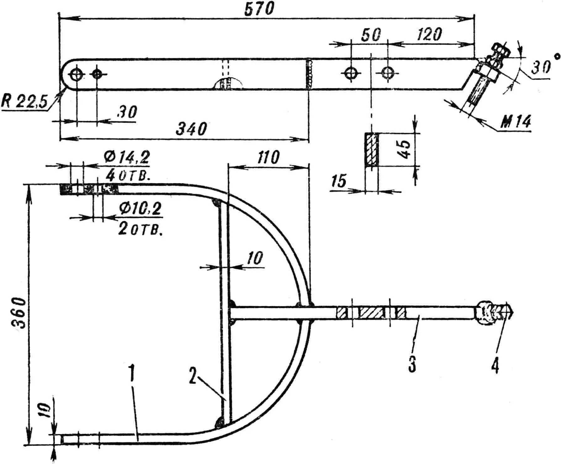
1 — arch, 2 — crossbar, 3 — beam, 4 — stop bolt for fine adjustment of the plow angle.
The tow frame is perhaps the simplest assembly of the entire machine in terms of design. It is welded from three steel strip parts and two M16×2 bolts. The front bracket has three holes for connecting the pivot-unit arch and the gearbox. The last two are elongated and serve for chain tensioning.
The U-shaped crossbar carries the bolts and springs for fastening the gearbox and the pivot-unit clamp. It is welded to the frame belt, in which a row of holes is drilled for the brake-disk locking bolt, the wheel-unit axle, and the mounting of interchangeable working implements. The latter are used when the tow is converted for soil cultivation in the garden. In addition to delivering water and working the soil, the walk-behind tractor can also be used for uprooting stumps and clearing boulders from fields. It is only necessary to remove the middle side member from the cart and install a tripod with a winch and grab. Having rolled the walk-behind tractor onto a boulder, you grip it with the grab and lift it. After placing a grate or wooden beams underneath, you put the boulder on them and haul it to the edge of the field.
“M-K” 4’86, O. OSTAPENKO, Vinnytsia
Recommend to read
 IN FLIGHT THE ROTORS
No, it's not helicopters. Speech will go today about snakes. You ask: can l find something in common between these very different devices? It is possible... the fact that the serpent... IT WAS CREATED TO FIGHT
He was born in the terrible days of August, forty-one. It was created for combat and was ready to fight. Fast, agile, and with powerful small arms and rocket weapons, finally, sheltered...
