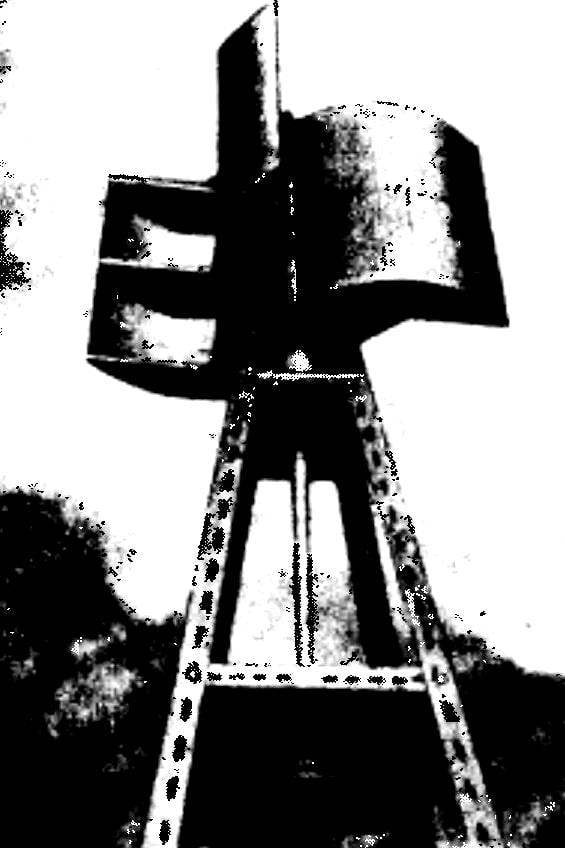
This design has a high adaptability, no missing parts and minimal need for machining parts. To undoubted advantages should carry the original solution of automatic installation of the rotor blades depending on wind speed. The engine can be used to drive a generator or pump. When the wind speed up to 30 km/h its capacity will be about 700 watts.
The rotor blades of a wind turbine made from two-millimeter plywood or sheet metal thickness 0.5—0.8 mm on a wooden or metal frame.
Fig. 1. Diagram of the machine of the vanes of the rotor. Letters show the positions of the rotor:
And — if wind is weak, B — moderate winds, in a high wind.
Figure 2. The action of air flow on the rotor blades.
Fig. 3. A wind turbine Assembly:
1 — top crossbar of the vanes of the rotor; 2 — blade rotor; 3 — the lower crosspiece of the rotor blades; 4 — pull-balancer, 5 — cross machine of the vanes, 6 — spring, 7 — rotor shaft Ø 30 mm, 8 — base of a wind turbine, 9 — pulley.
Fig. 4. Fastening of blades of the rotor:
1 — blade, 2 — the upper crossbar 3 to the lower crossbar; 4 — bushing, 5 — nuts with washers, 6 — nuts with bolts and washers.
Upper and lower brackets mounting the rotor blades are manufactured from steel strips with a thickness of 5 mm and collected on welding. The lower crosspiece to give it greater rigidity is enhanced by steel 5 mm braces, welded to her bottom. The crosses are mounted on the motor shaft locking screws M8 bushings frogs.
The machine of the vanes is designed to provide a relatively constant rotor speed regardless of wind strength. It consists of three parts — the d-pad, thrust spring.
The principle of operation of the machine is very simple. The incoming flow of wind spins the rotor. When the values of the wind speed spring machine, Contracting, establish the rotor blades into a position that makes maximum use of wind power (Fig. 1A). With the growth of the rotor speed with increasing wind thrust, performing both the functions of the cargo of beams, under the action of centrifugal forces begin to deploy the rotor blades, changing the angle of their installation (Fig. 1B; 1C). Thus the stability of rotation of the rotor.
Fig. 6. Cross slot of the vanes:
1 — strip crosspieces, 2 — bushing.
Fig. 7. The lower crosspiece of the blades of the rotor Assembly:
1 — cross strap 2 grommet mounting blades, 3 — strut, 4 — bushing axis.
Figure 8. The upper crosspiece of the mounting of the blades of the rotor Assembly:
1 — cross strap 2 grommet mounting blades, 3 — Bush axis.
Fig. 9. The blades of the rotor.
In the manufacture of automatic installation of the rotor blades, the main attention should be paid to the careful balancing of the whole structure. The stiffness of the spring, working in tension, is chosen empirically. If necessary, set the weights to the sides of the blades facing the axis of the rotor; this is achieved by the operation of the machine installation, when you increase the speed of rotation of the rotor.
Frame drive wind turbine is made of steel corners: 50x50x5. Platform frame to install the bearing housings are cut from steel sheet of thickness 5 mm. the Bearings you can use the following numbers: No. 106 or No. 206. The bearing housings are welded to the platform frame. The lower platform is movable for alignment of the rotor shaft.
According to the materials of the Hungarian magazine “Earmaster”
Recommend to read FIGHTER RECONNAISSANCE Yak-27R By the middle of 1950-ies the main front-line reconnaissance aircraft was considered to be Il-28R. But the car, excellent in all respects, by the time against the backdrop of recent... COLOR SOUND This attachment attaches to a regular television properties, a musical installation by changing the color of the image, respectively, the acoustic sound signal. When using the TV picture... Scroll back to top
 The editors constantly receive letters asking to tell about wind engines. In this publication we offer to your attention the device, published in the journal “Earmaster”.
