Momentary loss of electric power (for example, when triggered sensors) does not threaten loss of bees. Indeed, due to the high heat capacity, low thermal conductivity of honeycombs and honey temperature in the hive even after disconnecting the power circuit is held long enough for the redistribution of bees in each club.
Moreover, the continued inclusion of the heater is not allowed. Immediately triggered protection at an appropriate temperature sensor. Then instantly opens the power circuit of the thyristor VS1.
Capacitor C2 immediately begins to discharge through the resistance R7. The VT2 transistor will be closed and will open VТЗ (VT2 will cease to shunt). The result will light up the led VD2 (АЛ307) showing on the remote, which channel (the hive) have any disorder. Through the diode VDЗ opens the transistor VТ4, triggering a call-bell (alarm clock “Slava-5338”). And on the remote audible and visual signals will disturb the beekeeper as long as it does not fix the problems.
On a single chip DD1 collected three channel electronic thermostat. Look at the one of them first. The element DD1.1 performs here the function of the comparator with a threshold of 0.5 Usup; DD1.2 — the buffer providing the desired nature of the feedback loop temperature control.
Schematic diagram of multi-channel electronic thermostat for apiary
In the initial state (when the temperature is greater than the threshold) the resistance of the thermistor RK1 little. And at the entrance of DD1.1 voltage above switching threshold. And this means that the output of this element is low and the output DD1.2 — high, the Transistor VT1 is open and shunts managing the transition of SCR VS1. Therefore, the latter is locked, and the heater is disabled.
As the temperature decreases the resistance of the thermistor increases. Means of achieving the selected temperature the element DD1.1 definitely will switch. The high level voltage transfer DD1.2 to another state that closes transistor VT1. Then the current flowing through the resistor R5, open SCR VS1 and the heater will turn on.
With increasing temperature in the hive the resistance of the thermistor will decrease and there will come a time when the heater will turn off.
The temperature accuracy when using 10-Kopaonik RTDs of the series of KMT and MMT is about 1 °C. When using RTDs with a different resistance will have to change R1, R2 (and corresponding resistors in the other channels). And so that the sum of the values of R1 and R2 (with an average position of the engine “podstroechnye”) was approximately equal to the resistance of the thermistor at the operating temperature.
Rigged resistors provide a temperature scale. Graduate of her, placing the thermistor in a container of water on a hotplate. Temperature controlled by mercury thermometer.
To control the switching of SCR instead of a heater used in a table lamp. Rotating the handle of the corresponding “podstroechnye”, to achieve the switching of the thermostat. On a scale applied to the specific temperature. After calibrating all the sensors connect with the rest of the instrument shielded wire and placed in the hive below the frames.
In conclusion, on the elemental basis. All “trimmers” — SPZ-16, the other resistors — MLT. The SCR in each of the channels should open at the control current of 4 mA. When using semiconductor devices КУ201В (G, D, E) or КУ202В (G, D, E) with an operating voltage more than 50 V as the diodes VD10—VD17 acceptable Д242 or any other with a reverse voltage less than 50 V.
But when replacing thyristors on Simes-type Torah КУ208 you can do without diodes VD10—VD17, sapita heater (at point “B”) from one of the terminals of winding III of the transformer T1 (the second terminal should be connected with “earth”). Moreover, there are power thermostat without transformer (see chart). Then, all thyristors must be designed for a voltage of less than 300 V. This КУ201М (L, N, K), КУ202М (L, N, K). And diodes VD5-VD12 (with the same reverse voltage) are mounted on a finned heatsink with an area of 440 SMG through mica laying.
A. KUKHARENKO, Grodno
Recommend to read
 BUILDING A CAR
ACCORDING TO THE RULES. Twenty years ago there was an extensive debate: to allow or deny self-made cars? The idea of their buildings were resistant opponents. The latter believed that...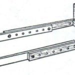 BED FOR GROWTH
Children, like mushrooms, grow by leaps and bounds: only yesterday everything was just right, and today, and the shoes are too tight, and the sleeves are short, and the cap is small....