CALCULATION OF SCREWS

CALCULATION OF SCREWSTo build templates of the screw (side view) for a given shape of the blade (top view) and the step there are two main methods of calculation: analytical and graphical. Usually based on the following characteristics: diameter, the relative width of the blade and step. Since the amount of slip is difficult to consider in advance, based on the geometric pitch.
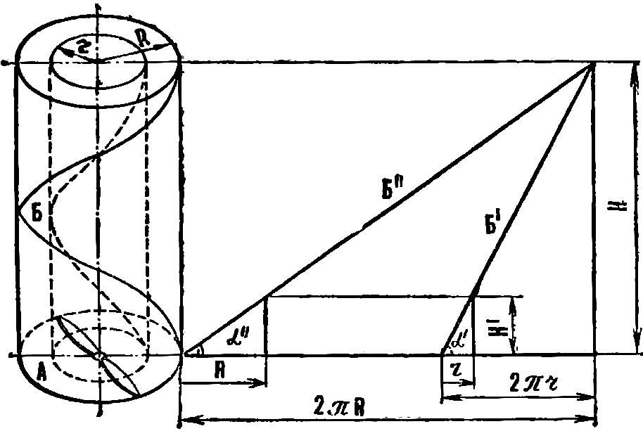
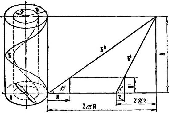
From figure 1 it is seen that the tangent of the blade pitch angle (α) in any cross-section associated with step (H) and radius (r) of the screw at this point the ratio:
 
tgα = H/2nr.
 
Fig. 1. Pitch and scan helix
Fig. 1. Step screw and reamer screw line:
R is the radius of the blade, r is the radius of the blade section, H is the screw pitch, is the circumference described by the cross section of the blades, 2nr — scan circle in the plane B — helix, described by the blade, B’ — scan helix in the plane α — the angle of the blade.
 
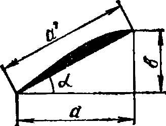
From the equation it is possible to determine the thickness of the blade in a side view (b) (Fig. 2) knowing the width when viewed from above (a). In the same section. located at a distance r from the axis of the screw, true equality:
 
b = a*tgα.
 
Fig. 2. The cross section of the blade
Fig. 2. The cross section of the blade:
a is the width of the blade when viewed from above, b — width of the blades from the side view, a’ — actual width of the blade, α — the angle of the blade.

The actual width of the blade (1) is determined from the relationship:
 
and1 = a/cosα, or
 
and1 = b/sinα.
 
Thus, using the first two dependencies, and figure 1 and selecting the type of screw top and its step, you can build a template of the screw seen from the side.
 
The procedure of analytical calculation of screw
 
1. For convenience of calculations it is necessary to calculate the so-called given step (H1):
 
H1 = H/2π.
 
2. On graph paper build a screw at the top view.
 
3. Perpendicular to the centerline of the blade hold the segments spaced from the center 30, 40… (r) mm.
 
4. Determine the tangent of the angle of each cross section located at a distance of 30, 40… (r) mm from the centre:
 
tgα = H1/r.
 
5. Determine the thickness of the screw seen from the side:
 
b = a*tgα.
 
6. Parallel to the centerline of the blade from the top view you need to draw a line where you restore the perpendiculars spaced from the center 30, 40… (r) mm. On them lay the magnitude of the thickness of the screw calculated for the respective sections.
 
7. Connect the resulting points with a smooth curve. (For convenience, the results should be put on the table.)
 
In practice, many modelers, especially beginners, use the graphical method of constructing the screw from the side. Since both methods are based on the same dependencies, the graphical method has advantages only in greater visibility.
 
The order of graphical calculation screw
 
1. On graph paper construct the screw in plan (Fig. 3).
 
Fig. 3. Build a template of the screw.
2. Perpendicular to the centerline of the blade guide segments, spaced from the center at 30, 40, etc. mm.
 
3. Parallel to a centerline draw a construction line. From the center screw, it will restore the perpendicular height H –1.
 
Analytical calculation of templates of the screw H = 180, H1 = 28,7
 
Analytical calculation of templates of the screw H = 180, N1 = 28,7
 
4. The end of the perpendicular connect the sloping lines with dots spaced at a distance of 30, 40… mm from the center.
 
5. On each inclined line is necessary to construct a right triangle. His basis will be equal to the width of the blade, and the height of its thickness from the side view in the corresponding section.
 
6. Parallel to the centerline of the blade guide directly where you restore the perpendiculars spaced from the center 30, 40… mm. Then they put the magnitude of the thickness of the rotor, defined from the figure for the corresponding sections.
 
7. Plotting points join with a smooth curve.
 
The table and figure 3 shows examples of how to calculate screw Ø 220 mm, pitch 180 mm for the engine volume of 2.5 cm3.
 
A. PIKELNY, head of airmodelling mug, Dnepropetrovsk

Recommend to read

  • MAIN BATTLE TANK T-90MAIN BATTLE TANK T-90
    The main drawback of T-72 tanks of all modifications, compared to other cars of the Soviet and foreign production of those years was the lack of an automated fire control system (FCS)....
  • ARMORED CAR IVECO UNDER THE BRAND NAME “LYNX”ARMORED CAR IVECO UNDER THE BRAND NAME “LYNX”
    Cars, army UAZ-29661-vehicle with engine ZMZ-5143 98 HP and an elongated UAZ-2966 motor 9МЗ-4219.1 84 HP, which in the early 2000s were equipped with the Russian army, created on the...