This night light is not afraid of shaking, drops, power surges and does not require special maintenance. For this purpose it is equipped with two types of relays: photos and acoustic. LEDs emit light only after dark, under the condition that the membrane of the microphone is sufficient sound effects (in other words, he must say, that he was involved). This mode of operation not only saves electricity but also creates a comfortable environment for guests.
Saving electricity today (when rates increase several times a year) is a crucial task for any prudent owner. Hams, and the more professionals who see the soldering station, a computer and an oscilloscope more often than the wife, have more opportunities to save electricity than people of other professions. One of variants of such savings is a simple device of light fired at the sound and at the same time controlling the overall room lighting.
If we assume that in 10 years the incandescent light bulb, turn on in the evening as sconces and night lights, will burn for 2 hours, then a 7300 hours. Perform simple calculations based on the lamp power 60 W and get 10 years of daily inclusions the consumption of one single lamp will be 438 kW. The cost of 1 kW of electricity in each region varies, but it (for completeness, economic feasibility) can calculate any reader. Let’s add the cost of the bulbs, which require replacement regularly about 4 times a year (the bulb is approximately 1000 hours of continuous burning, and frequent switching on and off its resources is greatly reduced). The need of replacement lamps brings to life human some discomfort—need to go (or go) to the store, spend time (which is now the prized “gold”), and possibly money down the road. Many useful things could be accomplished instead!
Electric diagram of automatic night lamp economical
On the contrary, economical night light to ultra bright LEDs with the node automatic activation when acoustic effects near it compares favorably with lamps with incandescent bulbs. The light from 10 led consumes 220 V no more than 60 mA when the power of light that rivals incandescent. Accordingly, consumption of the night light LEDs capacity will be 13.2 watts, which is almost 4.6 times less than with the “usual” lamp, which will produce heat losses in the led night light is minimized.
Some competition proposed device can be notorious energy saving lamps (ESL), a resource which (when working for 2 — 3 hours daily), according to manufacturers, will be 6 years.
Excellent color rendition comparable power ECL 11-15 watts, a solid “flicker-free” and “day” or “warm light” (quotes manufacturer of energy saving lamps) — all these parameters are not worse than the LEDs used in the device described of a lamp.
However, ECL with standard socket (socket) type E27, according to available data, out of order more often than once in 6 years—about once a year. And its average value (120 RUB. in the region of Saint Petersburg) is comparable today with the cost of 10 standard incandescent bulbs and is much higher than the cost of a set of LEDs for the nightlight. In addition, many items are in the radio Amateur “in the bins”. Thus, the economic feasibility of the proposed device are obvious.
In addition, repeating design, ham radio will gain invaluable experience, expand your knowledge, and if we show innovative thinking and will find ways to improve the electrical scheme and all the proposed design, it will go to the benefit of all.
Microphone amplifier the device is assembled on a low noise operational amplifier (OA) DA1. Its gain is determined by the ratio of resistances of resistors R4 and R5. For normal operation of the IC, the voltage at its non-inverting input (pin 3 DA1) should be approximately half the voltage on pin 7 (output to supply power). In the voltage divider to OPAMP consists of R1, R4 and microphone ВМ1. Resistor R2 sets the quiescent current ow at 180…300 mA.
Reinforced by a chip of DA1 the voltage of audio frequency is removed from the output of op-amp and through the separating capacitor C4 is supplied to half-wave rectifier diodes VD1, VD2. When the sound level is sufficient, the capacitor C5 is charged to a voltage of 2.5…6 In field p-channel transistor VT2 enriched offers. If at this time the phototransistor VT1’s not lit, the transistor VT3 is closed and the transistors VT4 and VT5 are opened, which leads to the ignition Ultrabright LEDs HL1—HL10. In practice, the number of the same type of LEDs, connected according to the diagram in figure 1, can vary from 5 to 10. The duration of the period after the onset of silence, during which the transistors will be designated by standing, mainly depends on the parameters of timing circuit C5R9. Connection diagram of transistors VT3, VT4 is a Schmitt trigger, which provides the high voltage VT5 transistor in a key mode. The capacitor C8 is designed for more precise shifting transistors of the trigger.
The sensitivity of the photocell to the artificial and natural lighting is set by resistor R7, it is higher, the greater its value.
The device is powered by mains voltage AC 220 V. a Voltage of +10 V±20% power control units is formed on the Zener diode VD4. Resistor R17 prevents de-energizing of the nodes in the closed high-voltage transistor VT5. When VT5 is closed, the voltage at the output of the collector relative to the common wire is 14…18 V, which is too little for the ignition of the LEDs, but enough to work the parametrical stabilizer on VD4, R16.
The resistor R18 is designed for the discharge of the capacitor C9 when the device is disconnected from the network. Resistor R19 reduces the inrush current through the bridge rectifier VD5 at power a nightlight.
The Pinout of some elements of the scheme
In design, you can use fixed resistors C2-23, C2-33, C1-4, MLT appropriate power. Trimming resistor R3 type RP1-63M, SPZ-19A, CP3-38A. Capacitor C5—tantalum-hicles with a small leakage current of the series K53-x, K52. absorbing the excess capacity of the mains voltage, the capacitor C9 — type K73-24, K73-17, K73-16 or imported counterpart for a voltage below 400 V and are specified on the concept of capacity. The capacitor C4 is definitely a film, for example K73-17 with a capacity of 1 µf and the operating voltage of 63 V. S6 Ceramic—type K10-17, KM-5. The remaining capacitor is the oxide, small. If possible, you should use branded, for example, firms Samsung, Keltron, Rubycon or domestic latest developments.
Diodes VD1—VD2 it is possible to replace the silicon thin series KD503, KD512, KD521, KD522. The Zener diode VD4 is replaced by КС406Б, КС210Ж, КС207А, Д814В, 1N4710, TZMC-10. The diode bridge VD5, DB104, DB107, КС407А, КС422Г or assembled from four rectifier diodes, e.g., type КД102Б, КД243Ж, 1 N4007. MOSFET transistor /T2 can be replaced by any from КП501, ZVN2120 or similar current key KR1014KT1 AND КР1064КТ1А. The Pinout of these and other devices are presented in figure 2.
Transistor VТЗ is replaced by any of the series КТ3102, 2SC1222, 2SC1845, and VТ4—series КТ940АМ, КТ969А, МРБА42, 2БС2330. Instead of a powerful high-voltage КТ851Б you can use 1ЅА1400, 2ЅА1776 or КТ9115А, КТ9178А.
Microphone — any small electret with a current consumption of 500 µa. The phototransistor with a black current of less than 100mA completely replaceable L51РЗ, L32РЗС or similar.
In the construction the author used imported Ultrabright led company, Kingbright 5 mm in a transparent enclosure. Using directories, trade organizations or manufacturers, you can pick up other LEDs with similar or better parameters. Instead of two or three of these in the diagram LEDs is permissible and even desirable to install one ultra-bright led of white color luminescence NSPW500ВS (5500…6400 MCD) or blue L7113РВС, L7113РВТ (450…1000 MCD, crystal alloy InGaN). Then for a normal illumination of the night light enough for 5-8 LEDs.
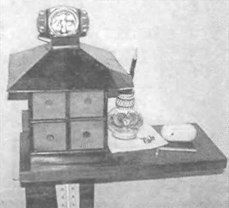
In addition, the application in the light of the LEDs of different colors of light gives softer, more natural “evening” lighting. Therefore, is indicated in the diagram LEDs HL1 —НL5 acceptable to use a led red glow L1513SRC/F (luminous intensity of 4,500 MCD), L1503SRС/F, L1543SRС/F domestic КИПД40С20-1/K4-L6 or similar electric characteristics. Instead НL6—HL10—green L1513SGC, L1503SGТ, L1543SGC or domestic counterparts КИПД40С20-1/L1-L6. The photo shows the appearance of the finished device in different States.
All parts are in the original placed in the housing of souvenir-candlestick “house” with dimensions 105x70x45 mm, and the Ultrabright LEDs in the housing of the miniature flashlight mounted on the “roof” of the candlestick. At the request of Amateur radio can be used for construction and other housing, such as “active plug”, “box”, “soap”. However, it is best to embed LEDs fits the regular housing of the portable lantern, which already provides space for seven LEDs NSPW500BS type and the same electrical characteristics and sizes (diameter 5 mm). On the back side of “house” you will need to drill three or four vent holes with a diameter of 2-2,5 mm.
Luminous flux from the led should not fall on the phototransistor (VT1). So it is fixed inside the housing on the side wall, the photosensitive surface on the outside.
ВМ1 a microphone on the opposite side of the housing, right next to the holes in the housing. A microphone using a foam gasket is fixed with glue “super moment”.
The establishment of a correctly assembled device is reduced to installation of the balance OU the selection of resistor R1, the threshold sensitivity of acoustic resistor R3 and light sensitivity resistor R7. For ease of use, perception of the “senses” of light sets the maximum possible. If the glowing LEDs the voltage across the terminals of the collector and the emitter of the transistor VT5 will be more than 7 V, replace this transistor is similar but with a large current transfer ratio base. If the microphone sensitivity is insufficient, then in front of the detector VD1, VD2 should install one additional amplifier stage of bipolar p-n-p transistor operating with a collector current of 300…400 µa.
In parallel with the resistor R7 can be set small button with fixation that will allow you to light the led regardless of the status of both sensors.
Since all the elements of the device are under voltage of the lighting network, to configure the finished product should comply with electrical safety measures. When mounting LEDs, you must observe the polarity and do not allow them to break the chain.
A. KASHKAROV, St. Petersburg
Recommend to read ACCURATE MARKINGS To spend simply a circle on a plane costs nothing with the help of a compass. But what if this line should cover a cylindrical billet? For a rough layout, you can use string or a rubber... CALLING IN A WHISPER Old alarm clocks and many doorbells and telephones emit a signal due to the blows of "hammer" metal hemisphere of the bell. If you are annoying it's pretty sharp rattling, stick a bell...
Scroll back to top

 In recent years, developers of electronic equipment for ham radio became available to the newest element base of leading foreign and domestic manufacturers, allowing you to create new versions of familiar domestic devices, significantly increasing their performance.