Stock (aka piston) is also made of pipe Ø 26X3 mm, the top of which is plugged with a steel disc 3 mm thick with welded thereto a lug joint. In the side wall of the welded stock and delivery fitting. In the lower end of the housing is screwed up the bypass valve with a loose fit ball Ø 14 mm. limit switches both have no balls.
After Assembly, the rod is turned (before fitting) on a lathe up to Ø 25,95 mm and polished.
Fig. 1. A pump with a hollow piston:
1 — frame 2 — hinge cylinder, 3 — suction fitting cylinder, 4 — cylinder, 5 — bolt tie M3 (3 PCs.), 6 — cap oil seal, 7 — rod, 8 — the hinge of the stock, 9 — stick, 10 — hinge, knob, 11 — delivery hose 12 receiver, 13 — output fitting 14, the bottom of the receiver, 15 — inlet fitting.
Sealing of the cylinder packing: two felt rings, cut out of the tops of boots, with stuffing cord between them, clamped by the cover with three bolts M8 of the screed.
The receiver serves to smooth out pressure pulsations of the fluid, represents a steel pipe with plugged ends, in its walls welded inlet and outlet fittings.
Top — handle, which is pumped liquid. It is attached to the eyelet on the cover of the receiver rasklapanje bronze rod Ø 10 mm. Bronze provides the durability of the joints and softens the knock during operation. (Such rods are applied in all joints of the pump.)
The pumped liquid is fed through the hose to the suction fitting of the cylinder. If the pump handle is pulled up, the stock will go after her. Under the rod (the ball its that time sitting in the nest) will create a vacuum. The ball of the suction valve rises and skips the liquid in the cylinder. Its maximum size — when fully extended stock.
During the reverse movement of the handle the suction valve is under fluid pressure closes the wastegate, on the contrary, will be opened, and the contents of the cylinder will direct on the discharge hose into the receiver.
With vigorous swing receiver will quickly fill and the liquid will start flowing from the output fitting to the hose, say, spray evenly, without pressure surges.
The second vacuum pump. Although superficially and even range of many units and parts of it like the first, everything works the same way. It cylinder not pumping fluid through and suck — pushes. To do this, it is welded to the valve body with the suction and discharge fittings (the latter has radial cuts to allow liquid under the ball) and the lug of the hinge mounting on the receiver.
Fig. 2. Vacuum pump:
1 — frame 2 — hinge handle, 3 — suction fitting cylinder, 4 — cylinder, 5 — bolt tie M8 (3 PCs.), 6 — cap oil seal, 7 — rod, 8 — the hinge of the stock, 9 — stick, 10 — pin cylinder, 11 — delivery hose 12 receiver, 13 — output fitting 14, the bottom of the receiver, 15 — seat 16 — cap receiver, 17 — inlet fitting.
Fig. 3. Design of the vacuum cylinder:
1 — housing seal 2 — flange, 3 — cylinder, 4 — bottom end cap (2 PCs), 5 — pin-guide ball, suction valve, 6, 11 — ball valve, 7 — suction fitting 8 — hinge lug, 9 — radial slits, 10 — inlet fitting, 12 — bulb socket delivery valve, 13 — valve body.
The gaps formed when welding valves with butt-end of the hydraulic cylinder, the closed segment with ear — plugs bottom.
The plunger is simpler here than in the siphon pump. It is a machined up to Ø 25,95 mm and a polished pipe, capped at both ends.
The design of the seal is the same: felt rings, lanyard, cover and three bolts-tie M8.
The receiver is the same only the top to his lid attached handle and wooden seat. Working with the pump is better to sit and your weight to stabilize the Assembly, as the handle moves not from the top down, but from yourself — to yourself. Changed and the place of its attachment: the primary hinge is placed on the frame.
The frame is the same as that of the first pump. The same hose and nozzle.
P. KOLESNIKOV, A. AMIN Kustanai
Recommend to read An irrigation ditch… in the garden Whatever is planted on a garden plot—flowers, vegetables, shrubs, or fruit trees—every plant needs regular, and often heavy and prolonged watering.
A simple device, successfully tested... DISKOBOLKA As well as natural and habitual in our apartments home libraries, does not surprise anyone today, and family library: records, magnetopulse, the compact cassette. The latter appeared... 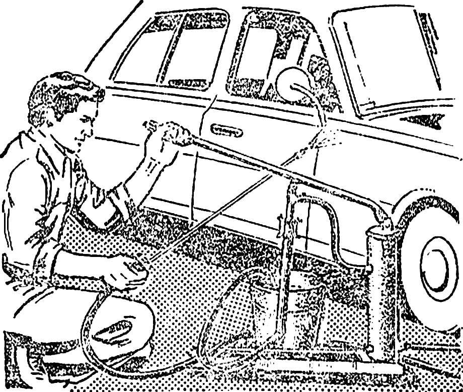
 Using pumps made by residents of the city of Kostanay Alexander Asinim and Paul A. Kolesnikov, it is possible to wash the vehicle, treat it the underbody rust inhibitor, wash a clogged radiator, to spray the bushes and trees or to water the beds in the garden.