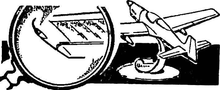
The fabric covering of aircraft during the second world war, good to simulate on the models-copies in the following way. Not yet primed with white enamel model according to the drawing axis and spaced edges protruding rigid elements (ribs, stringers, edges, edge of junction of the hard covering with canvas, etc.). Then on the markup pasted edges of the copper wire Ø 0,15—0,25 mm.
The wing, the empennage, the fuselage of the real aircraft represent the power part with a hard covering and non-coercive — plain — ribs ribs stringers and fabric covering with a little “slack”.
Pulling on a marking wire, reproducing the edges of the ribs and stringers, press and hold it one to two times with a brush dipped in Amalia, heavily diluted with acetone. Making sure that the wire is grabbed, a sharp Reachcom or a piece of a razor blade cut the excess ends. Thus consistently glued all the “ribs” or “stringers”.
Similarly simulates rigid elements on the sections of the fuselage model with the soft-soft skin. Due to the large length of the “stringer” and generally bad approaches (often interfere with the tail or wing) to provide the necessary stretch procrastinating pretty hard. In this case, the stretch is carried out with the help of pins. The ends of the wire are fixed on the bases of the pins stuck in body, with a little allowance from the end points of the “stringer”. After attaching the wires with a sharp knife cut the protruding ends and remove them together with pins.
Fig. 1. Simulated fabric covering.
Before primer (white nitroemali), with fabric covering, isolated, mask from tape, the form of which must exactly replicate the geometry of the edges adjacent to the “fabric” covering the areas of “rigidity”.
After that is applied to the soil. To remove the mask should be after treatment of the soil skin. During subsequent coloring due to the boundaries of a soil covering is formed is quite clear the visible edge of the rigid trim panel.
Fig. 2. The process of making “corrugated” skin:
I — tight laying of the wire; II — crop; III — thinning; IV — “rolling” on the forehead of the Aileron, the rear edge processing.
For models made in scale 1:50, the pitch of the corrugation should be 0.5 mm and the flange width of the ribs at the junction of the cladding of 0.6—0.8 mm. Height corrugation of 0.1—0.2 mm. in the same way running and trim the horizontal and vertical stabilizer.
To simulate corrugation before everything you must carefully prepare the surface of the wing for painting and outline the place of the ribs. Must be applied to the boundaries of the smooth areas of the wing (“the forehead” — to the front of the spar and ending), then on the surface of the wing is glued a thin copper wire Ø 0.15—0.2 mm — “corrugations” — a necessary step. The most suitable for this purpose is a wire, coated with varnish, the coils radios.
The wire is wound evenly, turn to turn to all the coils is parallel to the longitudinal plane of the model. The first 20-30 turns are fixed on a selected portion of the wing is pre-lubricated with liquid Amalita diluted with acetone. Once all the necessary wing surface is covered with a sheath and secured by a layer of Amalita, you can “liberate” areas of the wing with smooth skin, carefully cutting off the excess wire marking, taking care not to damage the fixed corrugations. Then the sharp tip of a knife to “thin out” through the round, carefully taking one or two later depending on the wire diameter. At the junction of the casings on the shelves “ribs” 3-4 procrastination decimated after coating they will proximityout wide “shelf” ribs. Hatches on the wing has a smooth lining is cut through the tip of a knife corresponding parts of the corrugation to the level of the surface of the wing. Then this site can be glued with a piece of tin foil. The obtained corrugation is finally fixed on the surface of the wing with three or four thin layers of liquid Amalita. Each subsequent layer is applied after the final drying of the previous one. It is necessary to keep enamel laid down a thin layer, without local streaks and clusters — otherwise delays in these areas may come off. Brush, use the softest, the direction of its motion is along the “corrugation”.
O. LAGUTIN
Recommend to read ESSENTIAL “EIGHT” Siberian airfields early 70-ies of the last century — the time of intensive development of the Tyumen oil fields — is hard to imagine without helicopters, created in OKB M. L. Mil. In... TRIPOD FOR MACRO PHOTOGRAPHY During normal photographing miniature objects - be it coins, insects, or drops of dew on the grass - is the involuntary trembling of the hands, especially with long exposures: they...  The fabric covering of aircraft during the second world war, good to simulate on the models-copies in the following way. Not yet primed with white enamel model according to the drawing axis and spaced edges protruding rigid elements (ribs, stringers, edges, edge of junction of the hard covering with canvas, etc.). Then on the markup pasted edges of the copper wire Ø 0,15—0,25 mm.
