
 One way to reduce interference in digital circuits, as is well known, is to install the ceramic capacitors in parallel with the power rails. The closer to the contacts of the chip capacitor is, the more effective his work is.
Most often in TTL and CMOS circuits of low and medium integration power pins are positioned diagonally, that is, the output with the maximum sequence number Nmax connected to a source of positive voltage +Ucc , and the output with the number Nmax/2 — to the common GND wire.
For such a case abroad developed special sockets with built-in capacitors (0.1 UF x 50 In), for example РF08К—РF40К or LC14К0—LC20К0 company Microparts-Garry Electronics.
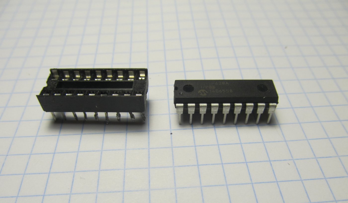
However, a similar design can be made independently using a cheap plastic DIP sockets black manufacturing countries in Southeast Asia.
Capacitor C1 is located within the through-slot width of 2 mm (narrow panel) or 10 mm (wide panel). The height of the condenser should not be more than 5-5,5 mm, so as not to interfere with the installation of the chip. The value of C1 is selected in the range 0,015—0,15 µf at work with signals up to 10-20 MHz and 1000 pF and 0.01 µf on the higher frequencies.
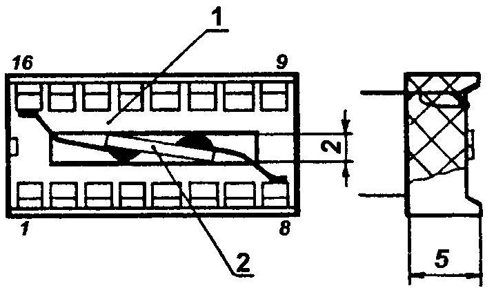
With no interference capacitor will not:
1 —socket DIP-16; 2 — built-in noise condenser
For a narrow socket can be used ceramic capacitors of type KM-5, K10-17. For a wide socket handy cylindrical capacitors A (mono-axial) with a diameter of 2.5— 3.8 mm and length 3.8—7.5 mm Philips (capacitance range 10 pF to 1 µf, working voltage 25-100).
The Assembly technology of particular complexity is no different. Initially, the contacts 8 and 16 of the socket gently push 1-2 mm above the surface and oblizyvaet side. The terminals of the capacitor are formed on the spot. Then solder them to the tinned surfaces. After that, a soldering iron gently pressed against the terminals of the capacitor in plastic body panels while simultaneously guiding a pair of tweezers contacts in the seats. Solder residue removed with a needle file. The link quality check using an ohmmeter.
Soldering should be minimal, despite the fact that the conclusions of the foreign sockets allow heating for 5 s at a temperature of soldering 260 °C.
Similarly, you can modify the sockets with pin count from 14 to 40. Their applications: breadboard, schematic, removable, ROM, RAM, devices with rich installation. In addition to saving space on the circuit Board such panels increases the noise immunity of the equipment where they are installed.
S. ROMIC, Chernigov, Ukraine
Recommend to read
 LOFT WITH COMFORT
The living area of this summer house is almost twice the space it occupies in the garden. The secret is simple: the previously empty attic was turned by skillful hands into another... FOLDING HEADSETS
It is designed for area in the suburban area, the walls of the house with a sun or, on the contrary, the shady side —where someone more like it. To set this headset comes with a table...
