However, in contrast to the prior art, in ‘my design has the diode VD1, the operation indicator lamp HL1 and resistors RZ—R6. Moreover, the “shells” R6 is provided with a scale with divisions of 5, that allows acceptable error rate in the test voltage circuit.
Structurally, the probe-voltage meter is made in the form of a handy cap with mounted inside the electronics, filled with epoxy resin. At the front (pointed) part of the device houses the probe ХР1 and a rear variable resistor R6 with a scale and a pen-pointer. On the lateral surface of the cap removed the light and flexible insulated wire with second probe 2 (for example, acute copper pin or clamp type “crocodile”).
circuit diagram (a) layout and (b) a self-made probe-measuring voltage:
1 —body; 2 — probe needle ХР1; 3—diode; 4 — Board with mounted on it and the electronics; 5 — led; 6 — variable resistor; 7 — scale (scale 5); 8 — handle-index voltage; 9 — a flexible insulated wire (with probe 2 at the end or clamp type “crocodile”); 10 — insulating filling (epoxy resin)
Installation the electronic parts of the device can be anything, including attachments. But better, of course, to solder everything on a 1.5 mm circuit Board from a one-sided foil of the PCB or Micarta.
And tuning of the instrument, of course, should be done before installing the Board into the case and fill it with epoxy. Exposing DWI Joc resistor I6 to the middle position, you should make sure that when applying for both of the probe is negligible AC voltage indicator Н1_1 barely lit, while at large — is brightly lit. The lower limit of the display (5) specifies the selection of the nominal value I5, and the brightness achieved by resistor R4.
The same operations are performed during connection (in compliance with the required polarity) of the probe device to the DC circuits. Reliability hopping off led HL1 is achieved by adjustment of the par value of R2. After the calibration of the scale of the variable resistor R6 (the price of one division, as already emphasized, should be 5) “electronics” of the device can be considered ready for final installation in the hull and fill with epoxy.
A. GUSHCHIN
Recommend to read COUNTRY MOTOR ASSISTANT Several years ago, our family purchased a summer cottage that had not been cultivated for a long time. An attempt to dig it up by hand was unsuccessful and we were forced to hire people... SINGING PENCIL CASE I propose an extremely simple structure of the electronic musical instrument. Its structure is clear from the drawing and the concept. The musical range of 2-3 octaves. The... 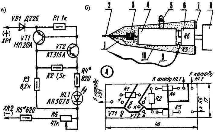
 Love to collect basic and necessary household appliances. One of them is the homemade probe, which is designed not only for “continuity” of the electrical circuits in the range of 5-300 In, but also to determine the type, polarity, electric current, measure the voltage from 5 to 60 V — stand on the court readers of the respected journal. The basis of the device is a transistor analogue of the thyristor, addressed at length in “Modelis-the-designer” №1, 1999.