 As a hobbyist designer with years of experience and a former captain of the regional team sports radiointerview (the hunt for “foxes”) offer a development designed to significantly improve the organization and conduct of training, competition, as well as to facilitate to beginners the way to the fascinating world of radio sport. In essence, this is a homemade compact and reliable transmitter “Fox” (PL). However, it is assembled by an improved wiring diagram, with keying in the power circuit of the crystal oscillator (Fig. 1).
The increased stability of the transistor VT1 in a larger interval of supply voltages and temperatures achieved by the introduction of an additional resistor R2 whose value is 10 kω. The capacitance of the junction in the output stage is increased, and in the chain of manipulation, on the contrary, much reduced in comparison with known industrial and ham radio PL.
Power to the terminal stage and the displacement at the base of the transistor VT1 of the driving generator is supplied constantly. Ensuring minimum transients when operating the transmitter, this leads to a significant improvement in the quality of the radiated signal. A small capacitance of the capacitor in the circuit of manipulation and are constantly arriving at the base of VT1 bias voltage create favorable conditions for the fast excitation of the quartz resonator ZQ1 and generator, eliminating the shortening of the PL signal to make inconspicuous a forced frequency deviation when operating (transmitter works without the annoying “kakania”).
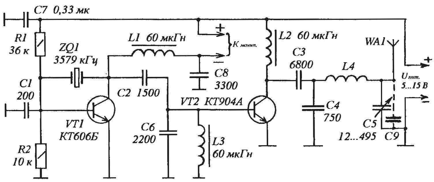
Fig. 1. A circuit diagram of a homemade transmitter for “Fox” manipulation of the crystal oscillator circuit power
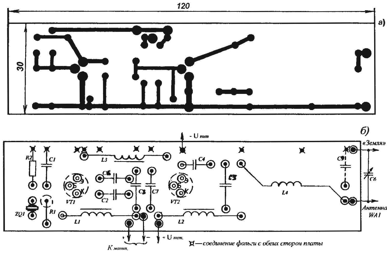
Fig. 2. Circuit Board with the printed conductors (a) and side parts installation (b)
The advantages of the development, proposed by me, there is a substantial reduction of current in the circuit manipulation PL. “Clochette” only I a of the transistor VT1, and not the entire transmitter. The voltage drop on the key transistor is reduced, but in one only, the master oscillator that makes the manipulation more economical and promising.
However, somewhat saddened by the current flowing through the voltage divider R1 — R2 in the absence of the transmitter signal. However, the magnitude of this current is insignificant, being a kind of fee for quick manipulation and improved the thermal stability of the cascade, besides the two-minute “pause” is possible, it appears to remove power from the transmitter with… training manipulators electronic control clock is well known to many radiosporten. And if a slight current here is spam, it is recommended to connect the top (see Fig. 1) the output of the resistor R1 with the “minus” chain of manipulation, disabling it from the “plus” of the power source. Unfortunately, we have to put up with a small decline in the quality of the manipulated signal PL.
Circuit manipulation can also include p-n-p type transistor KT816. Its emitter is thus connected to “plus” chain of manipulation (and therefore +Usup), collector — with a “minus” (for wiring diagram — right terminal of the inductor L1); a base — with the midpoint of the two-element voltage divider, one resistor with value not exceeding 1 kW, soldered between the base and the emitter of this semiconductor triode, and the second, the resistance of 1-100 ohms, between base and collector KT816 VT1.
The selection of the second (larger) resistor depends on the voltage VT1 is saturation key, and the mode of operation KT816, which should not only provide the operating current of the transistor oscillator, but not to go beyond the allowable current its base.
Setting a base KT816 on “building” the so-called capacitor RF decoupling, matching its capacity to effectively influence the shape of the manipulated pulses. Moreover— feed and manipulator, and the transmitter of the total battery.
Now about the features of the design. Schematic diagram of PL mounted on a printed circuit Board 120x30x1,5 mm of the bilateral foiled fiberglass (Fig. 2). The conductive copper layer from the system side parts preferably do not delete, let it serves as a screen against interference and radio interference. In places, designed to “electric transfer” to the corresponding printed contact pad and marked with a cross, set with a wire jumper or the findings of subsequent bilateral propanol. Holes that must be electrically isolated from non-remote copper layer of the screen, razzenkovyvajut from the setup details.
The resistors used in the transmitter, MLT-0,25. Capacitors, fixed — of a series of K10-7, KM, KT; “shells” is one section of the block KPE from any broadcast radio.
Quartz crystal (3579 kHz) is also not scarce, as high-frequency chokes L1 — L3 type DP-0,6 (each inductance of 60 µh). But the 1.4 coil is the output oscillating circuit homemade, frameless. Performed on the mandrel with a diameter of 14 mm (e.g., galvanic cell 316, or AA), it contains 58 turns ПЭВ2-0.43.
The winding length of 35 mm. And the coils subsequently spread, they fasten into a single unit by bonding to the PCB with molten wax (from candles).
In dense mounting (in one case) transmitter and a positioner are preferably separated from each other by a metal screen. However, it should be noted that during testing of the equipment no screens were used; the units of both devices were located two feet from each other. The results have been very encouraging.
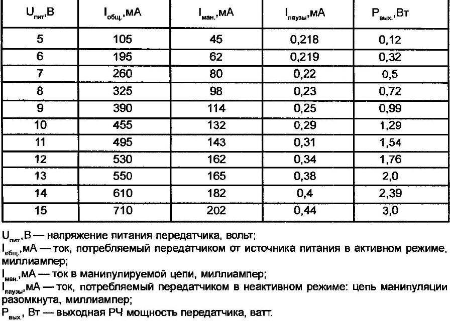
The following experiment on the transfer-receiving call signs “Fox” was held in the conditions when each of the transistors PL had its own radiator for cooling and the power supply voltage was 12 V. But it soon became clear: the manipulator and the transmitter itself can do without any… radiators. Even with the “kluchevaya” power to the entire transmitter (Usup 15V!) temperature key transistor VT1 (КТ972 when basileios, electronic manipulations) did not exceed 50’C. Transistor VT2 was even colder. Although the transmitter worked on these tests two cycles for five hours, again — no failures (see table).
Test results transmitter
The official borders of Tyumen also participated in the experiment, estimating within the city limits the signal using connected equipment (antenna — outside sound from 7 to 9 points on the “decibel” scale). Estimated signals “foxes” and authoritative specialists using Amateur VHF repeater, and also on the city’s VHF network. The results of the tests, as before, is good.
But the opinion of the regional station of young technicians. When testing in the city when the model PL worked on the G-shaped antenna with a length of 8 m, located on the roof of a two story wooden building, and the reception of signals “foxes” were out of line-of-sight (brick and concrete buildings) in the radio room on the 4th floor of Obsut, the audibility of the signal received by the direction finder “Wood is 3.5” (Patriotic) and “GREIF” (German), ranged 2 points. Mentioned frequency deviation, shortening of elements of marks, and loss of “points” in a call “MINE.” And this is when the manipulation of the transmitter “Fox” STILL, the most common way.
With the transition to the NEW PL mode, most fully realized in the above structures, the power of the processed signal has increased to 4 points; “points” was perceived not less clearly than “dash”, there is no frequency deviation was observed. That is, a home-made transmitter with keying of the crystal oscillator on the food chain have shown their potential.
V. BESEDIN, Tyumen
Literature
E. Sukhoverkhov. Automatic transmitter for sports radiodirection finding Search the Best design of the 29th and 30th exhibitions of creativity of radio fans/—M.: DOSAAF, 1984, p. 21-24.
Vladimir Besedin. “The Fox” program—the journal “modelist-Konstruktor”, 2002.
B. Viktorov. Manipulators for training Lis — journal “modelist-Konstruktor”, 2002.
Recommend to read
 THE BARS ON THE TIRES
The idea to build the Rover on low-pressure tires came to us with father after he was unable to rise to the snowmobile "Buran" to "Lunar glade" in Arkhyz. The design of the machine —... WITHOUT PEGS
Often at home you want to hang for drying items that cannot be secured with pin (for example, snails tiered photoback). Succeed with a string tied to nails or sticks out in any hole...
