 The device was created to check the capacity of Nickel-cadmium and Nickel-metal hydride batteries, but they can check for any small capacity batteries and dry cells. The device is composed of two parts — digital multimeter and active load. The voltmeter consists of a transmitter “amplitude-time” on the element DD1.1 and the transistors VT1 — VT4, generator counting pulses on DD1.2 and pulse counters for DD2 — DD4.
Generator DD1.1 (assembled in the Schmitt trigger) generates a sequence of short positive pulses with a repetition period of about 0.5 s, and, opening the keys on the transistors VT1 and VT2, charge capacitor C4 from the source of the measured voltage. During the charge, you also reset the counters at the input R to prepare for the cycle count. After charging starts discharge C4 through the current generator to VTЗ (linearizer level) and the transistor VT4, which in turn, through the logic elements DD1.4 and DD1.3 to permit the passage of the counting pulses from generator DD1.2 (assembled as DD1.1, also in the Schmitt trigger) on the counters DD2 — DD4. Thus, the counting of pulses occurs during the discharge of the integrating capacitor C4. The discharge time is proportional to the amplitude of the measured voltage. The rest period after the reference (category C4) to the leading edge of the next pulse falls on the indication.
The active load consists of a timer (for DA2) and load devices (transistors VT5 and VT6). Composite transistor VT6 when you enable the timer in its transition of “collector— emitter” and the resistor R16 forms a load resistance to the battery depending on the current set by resistor R13.
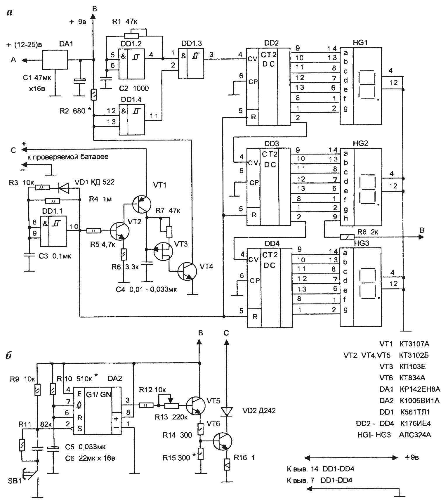
A circuit diagram of a digital voltmeter (a) and active load (b) of the device to check battery capacity is low
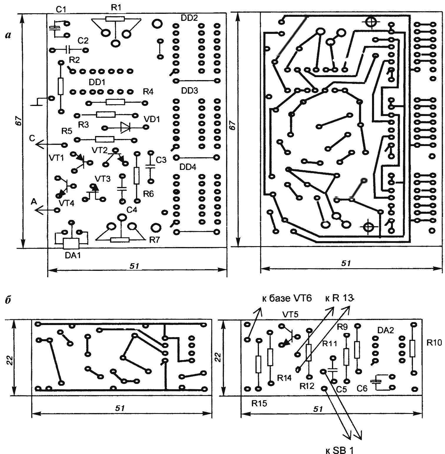
Topology of printed circuit boards and location details when installing the voltmeter (a) and active load (b)
Setting of the voltmeter is as follows. On the input regulated supply voltage 3 to 5 V. Resistor R7 is set the corresponding voltage. Then, the voltage 10 — 15 V and at a certain nonlinearity is adjusted by the resistor R1 or R2. The operation is repeated until the installation of linearity.
The scale knob of the variable resistor R13 need to calibrate in currents up to 2 A. of 2.5 For the calibration it is convenient to use the power supply current of at least 3 And with the ammeter by connecting the output of the power supply to the terminal, and periodically pressing the button SB1.
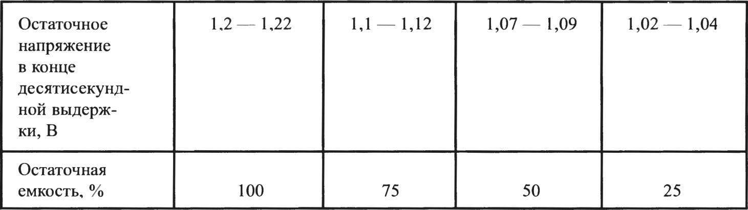
Rules of use of the device the following. Connect the output to the measured battery or the element and measure the voltage. Calibrated resistor R13 to set the load current of 1.5 — 2 E (E — capacity battery or A. C. element in the Set current is not changed depending on the measured voltage of the battery.). Leaving the output terminal by pressing the SB1 button to start the timer, which connects the transistor VT6 to the battery for about 10 seconds. At the moment of shutdown timer need to measure the readings of the Residual capacity of a battery roughly we can see from the table (in terms of one element).
The design and details. Transistors (except VT3) can be with any alphabetic index. VT6 — part, you can apply КТ827А. Capacitor C4 — type K73-17. Resistors R1 and R7 desirable multi-turn — type SP5-2; R16 is C5-16МВ1 0.75 to 1 Ohm, or is composed of two MLT-2 1.5 — 2 Ohms, or wire.
Transistor VT6 need to install the radiator with the effective cooling area of at least 60 cm2. As a small radiator mounted stabilizer DA1. The diode VD2 can be installed on the radiator VT6.
The device is powered from the power adapter with an output constant voltage 12 — 25 V and a current of at least 400mA.
The digital part can be replaced with a multimeter, providing at the load side of the diagram an extra socket to connect. The power scheme of the load should be stable, voltage of 5 — 9. Graduation of the scale is made for a specific voltage.
Combining the insights of A and C on the schematic, a voltmeter can be used as automotive (on-Board) and display.
V. Kuz’MIN, g. Cheboksary
Recommend to read
 DESK OF SPEED SPECIALIST
"Wow, beautiful..." — that was the unanimous opinion of the participants about our high-speed cord models. After a short discussion, the boys made a "sentence" is a set of custom-making... “BREAKING” MALOGRUZOVAJA
Like many readers of the journal "modelist-Konstruktor", fond of design — so more than the others interest me in the magazine sections of the "Social Bureau" and "Small-scale...
