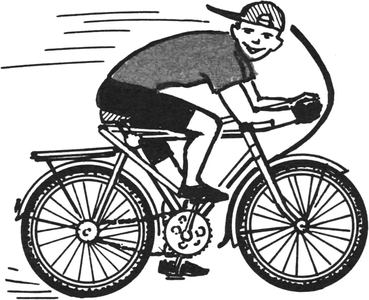
PEDALS PLUS A LEVER
They say inventing the bicycle is a thankless task. And yet… And yet… This machine, refined in design over many decades, never ceases to excite inventors’ minds. Recall that “bicycle” from Greek means “fast feet.” But why only the feet? There are also the arms. Can’t their strength be used for extra propulsion as well? At the same time, it is also training for them.
The easily removable, simple and reliable hand attachment I made has proven itself in practice and can be fitted to any bicycle with a triangular frame. It works by converting the reciprocating motion of a hand lever into rotation of the crank of the pedal drive. One hand (left or right) holds the handlebar, while the other works.
The attachment consists of a double-arm lever bent from half-inch water pipe, with a standard bicycle grip fitted tightly onto its end. At the bend of the lever a bearing ring is welded on, through which an Ø 8 mm axle with a lock washer at the end is passed. The semicircular thrust bracket is made of sheet steel 3…5 mm thick to match the diameter of the bicycle frame tube and is welded to the axle. It takes the main dynamic load during operation. An M8 nut is screwed tightly onto the threaded end of the axle.
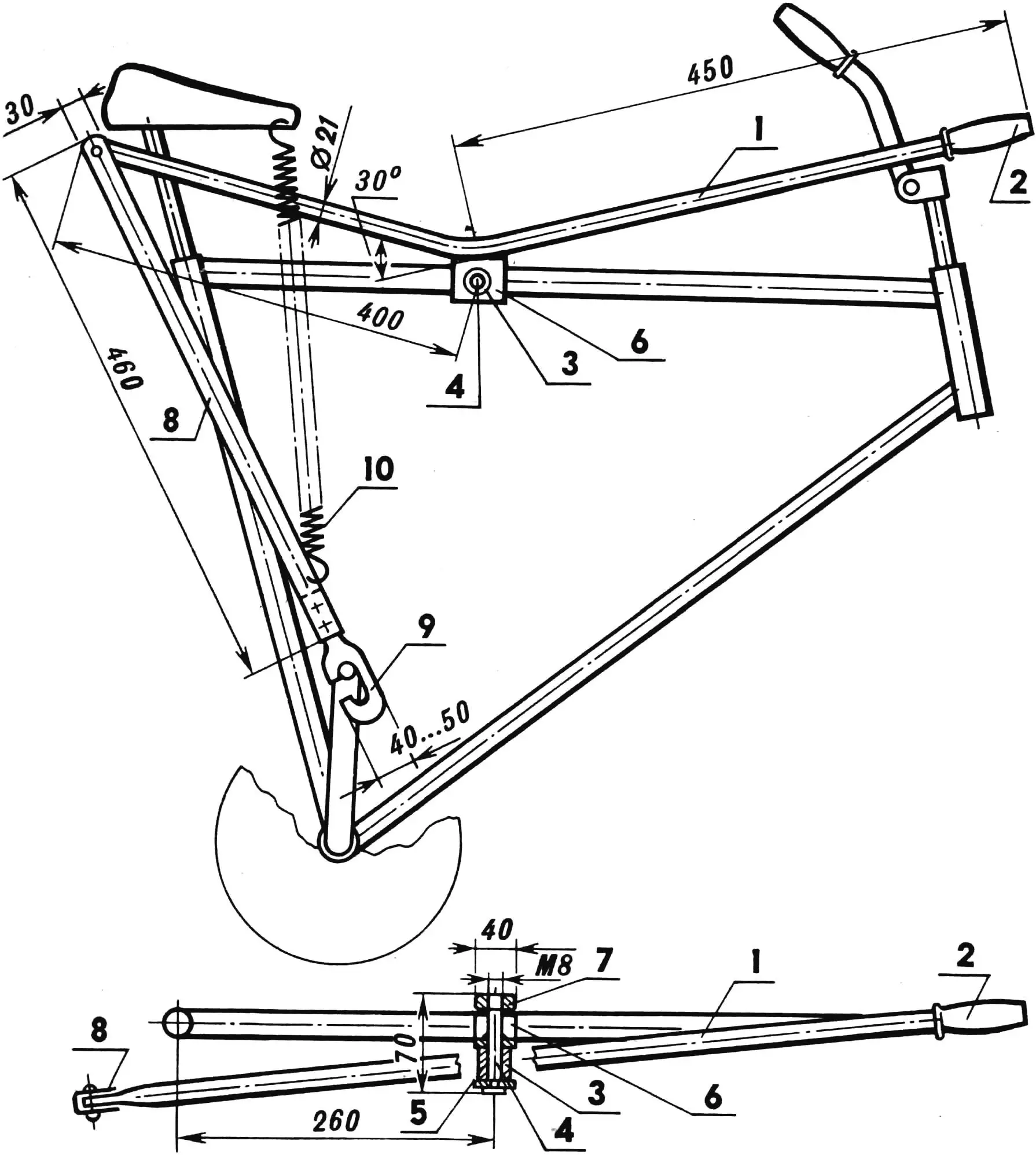
1 — double-arm lever (1/2″ steel pipe), 2 — grip (from a bicycle handlebar), 3 — bearing ring, 4 — axle, 5 — lock washer, 6 — thrust bracket, 7 — M8 nut, 8 — rod (from steel strip 1…2 mm thick), 9 — catch (steel strip 3 mm thick), 10 — return spring (from an expander).
To fit the attachment, you only need to drill an Ø 8 mm hole in the top tube of the frame, which barely reduces frame strength. A rigid rod is hinged to the second end of the lever, flattened with a hammer. It can be made by bending a steel strip 1…2 mm thick into a U shape. At the lower end of the rod a sickle-shaped steel catch (3 mm thick) with a C-shaped slot is attached by rivets or welding; the neck of the bicycle pedal axle enters this slot. The end of a flexible spring (for example, from an expander), linked to the saddle, is also fastened there.
As the drawing shows, the attachment sits between the cyclist’s legs and does not interfere with pedaling. It lets you bring the arms into play alternately. When the left hand holds the handlebar, the right works both away from and toward the body, turning the pedal crank through the rod. The catch can be easily disconnected from the transmission by taking it out through the slot opening. The spring automatically returns the attachment to a compact idle position.
I have been using such an attachment for a long time — mainly when riding a road bicycle with a load over hilly terrain at low speeds.
A SHIELD AND ARMOR
Surely every cyclist in windy cold weather feels a secret envy of car drivers, who fear neither wind nor cold and are reliably sheltered from bad weather by the cabin. Can’t a bicycle be fitted with at least a windscreen — like those on motorcycles, for example? It turns out that it can, and it is not too difficult.
For two autumn–winter seasons already I have been fitting my bicycle with a simple, easily removable front shield consisting of only two parts: an apron of aluminum sheet 1…2 mm thick and 1500 mm long, and a rectangular window of acrylic glass. This practical design was made possible by the distinctive handlebar that has recently been fitted to racing bicycles. In principle, though, it also suits road bicycles of any make. The shield protects against the cold airflow, sharply reduces static load on the spine, makes pedaling easier, and cuts air resistance.
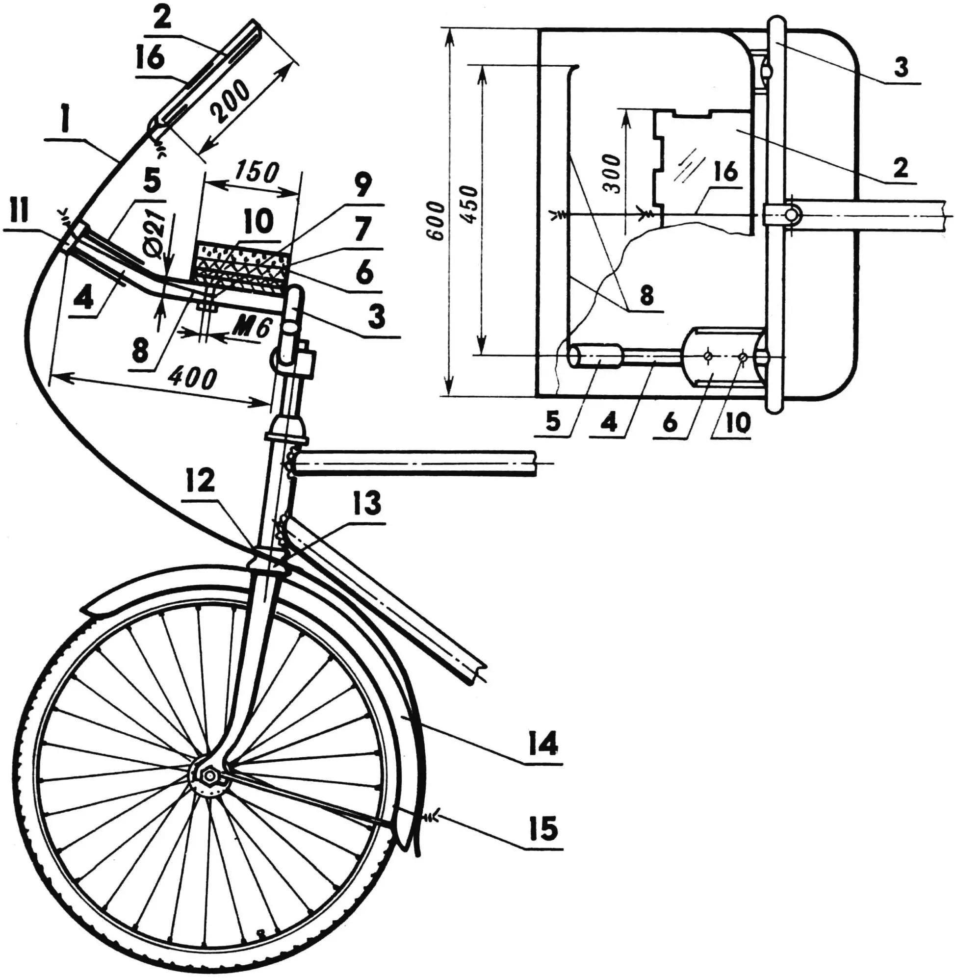
1 — apron (duralumin sheet 1…2 mm thick), 2 — glazing (acrylic glass 3 mm thick), 3 — handlebar, 4 — tubular brackets, 5 — grip, 6 — armrest, 7 — pad (foam rubber), 8 — wire fastening of the apron, 9 — loop, 10 — armrest mounting screws, 11 — rubber gasket, 12 — cutout for the steering column, 13 — front-wheel fork, 14 — front mudguard, 15 — wire clamp, 16 — glass fastening clamp.
If you weld two bent half-inch tubes to an ordinary handlebar, fit them with grips and mount armrests bent from thin aluminum sheet with foam pads, riding comfort will increase substantially. Attaching the fairing to such a handlebar is very simple. Just take two pieces of wire with loops at the ends, pass the armrest mounting screws through them, then twist the protruding wire ends on the outside of the shield after passing them through rubber gaskets — and the fastening is ready. In the apron you should also cut with a chisel a Ø 33 mm hole for the fork axle. The lower end of the apron is pulled to the front fender with a wire clamp. The same kind of clamp can also secure the glass.
I think you will appreciate this shield when riding in cold weather.
THREE SPEEDS FOR A ROAD BIKE
Which touring cyclist has not felt muscular satisfaction from riding multi-speed lightweight road bikes? One movement of the lever — and you climb a hill easily or speed briskly along a flat highway. Unfortunately, such bicycles are seen for sale less and less often. Yet turning any road bicycle into a three-speed one while retaining pedal braking is not that difficult.
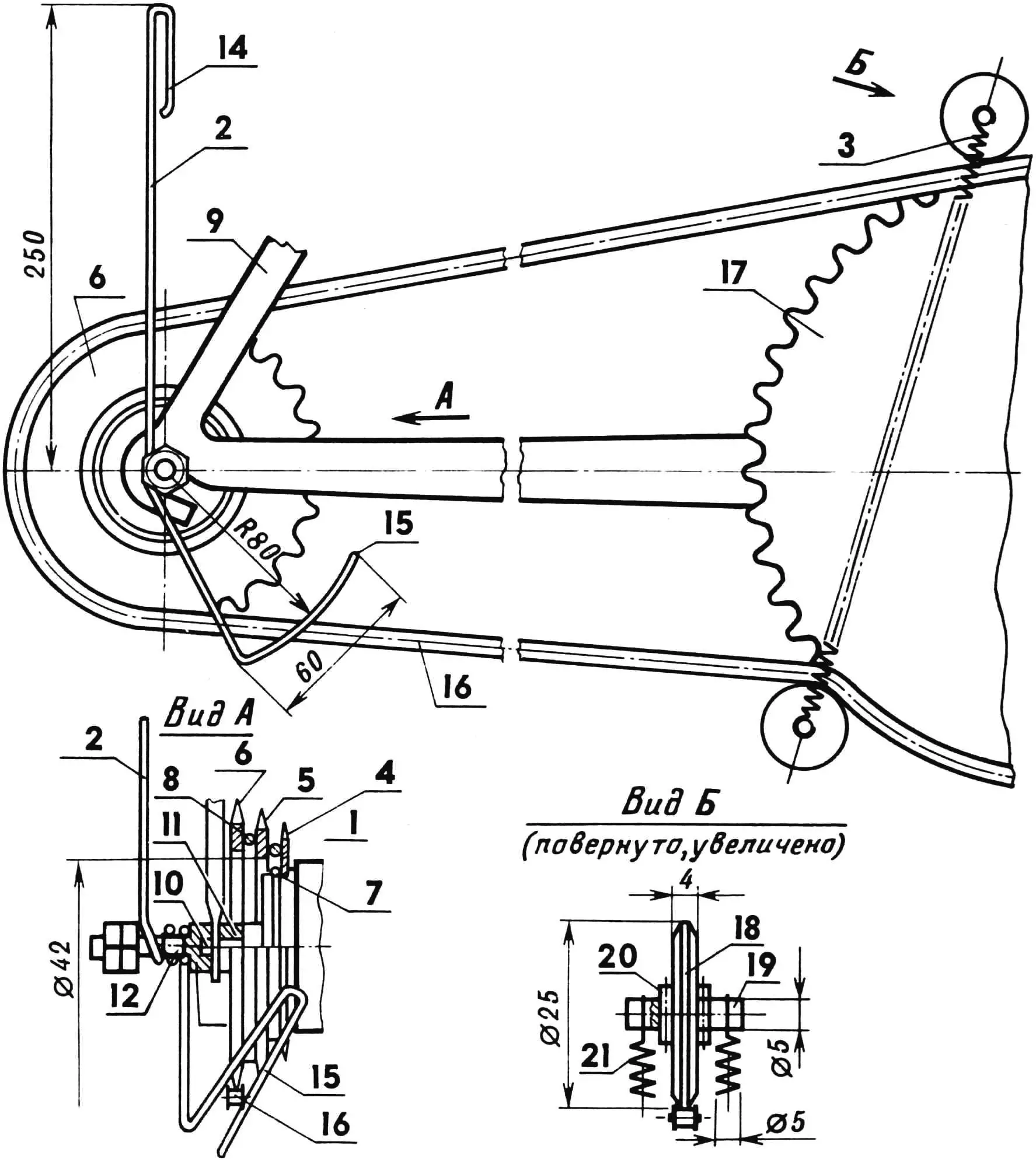
1 — spacer ring, 2 — gear-shift lever, 3 — spring chain tensioner, 4 — sprocket (z=15), 5 — sprocket (z=19), 6 — sprocket (z=26), 7 — lock ring, 8 — spacer ring, 9 — frame, 10 — rear-wheel axle, 11 — bushing, 12 — special nut, 13 — special-nut stem, 14 — handle, 15 — spiral groove, 16 — lower run of the chain, 17 — bicycle drive sprocket, 18 — roller, 19 — axle rod, 20 — pin, 21 — spring.
The drawings show the design of a homemade gear shifter. It consists of a multi-step sprocket cluster, a shift lever, and a spring chain tensioner. The 15-tooth sprocket is taken from a “Salyut” bicycle (they are sometimes available); the 19-tooth sprocket from an ordinary road bicycle; the 26-tooth sprocket from an old children’s bicycle. On the last two sprockets the inner diameter is bored out to Ø 42 mm to give access to the lock ring. Rings bent from Ø 5 mm wire are placed between the sprockets, after which the rings and sprockets are tack-welded — and the cluster is ready. A bushing is placed between the frame and the rear-wheel axle, and the axle is tightened with a special nut that has a stem on which a shift lever of Ø 4 mm steel wire is spring-mounted, with a handle and a spiral end forming a groove that engages the chain. By turning the lever you can move the lower run of the chain from one sprocket to another while slowly turning the cranks, as on a lightweight road bicycle. Fine adjustment and shaping of the lever are done on the bike.

A spring tensioner is freely mounted on the large sprocket, embracing and pressing the chain runs. It consists of two rollers freely fixed on bronze rods with pins. The ends of the rods are pulled together by two springs that keep chain tension both when pedaling and when braking.
“M-K” 5’94, V. GAVRILOV
Recommend to read
 FROM ZAPOROZHETS — BAGHEERA
a deep fascination with the technique came to me in youthful years, when he began not only to repair the scooter, but to collect them from different old parts. Then, growing up, over to... “CLOSET” ON ONE LEG
Periodicals are expensive, but still they are discharged, because it is difficult to imagine today's life without Newspapers and magazines. Given that each family member has their...
