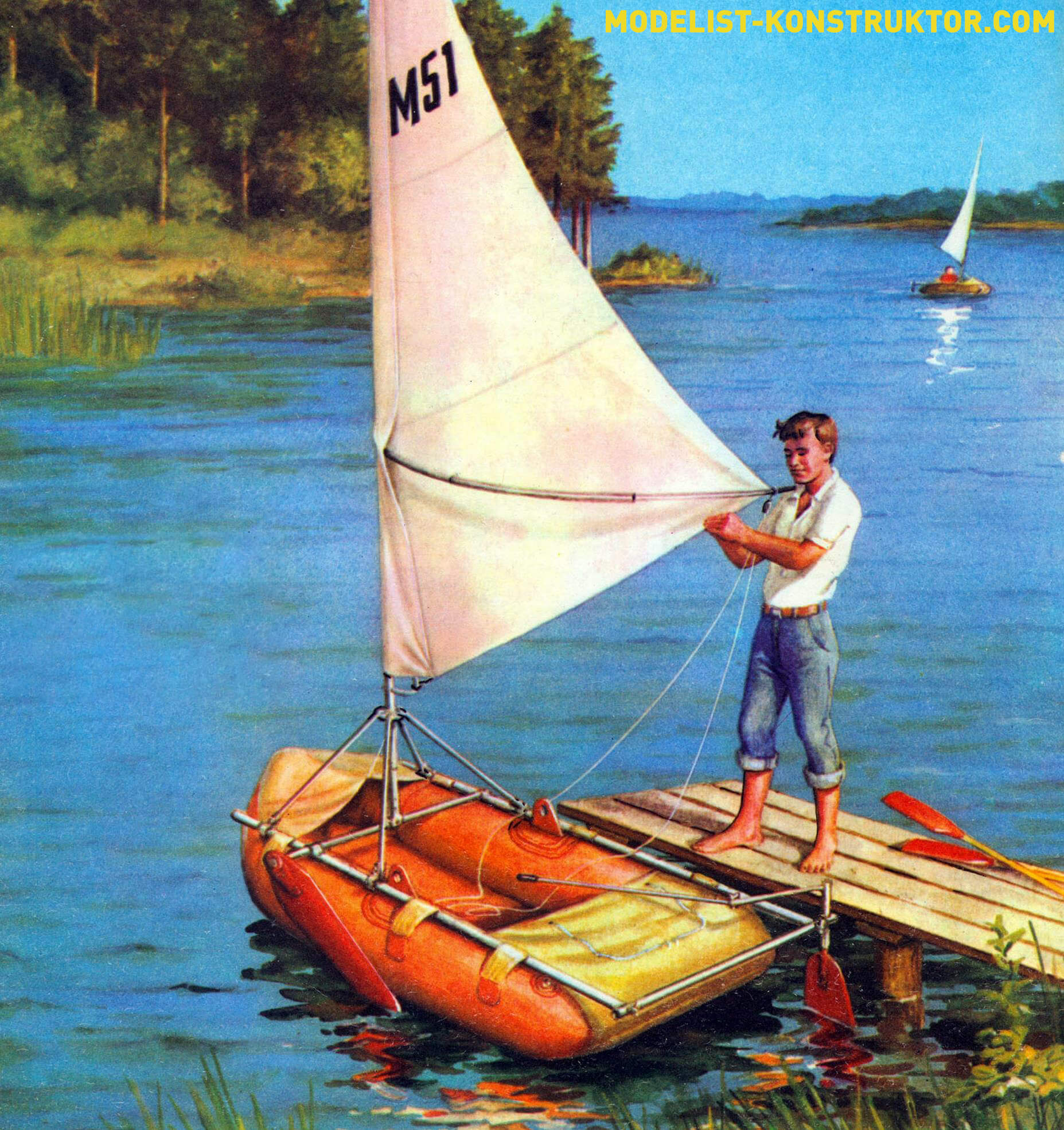
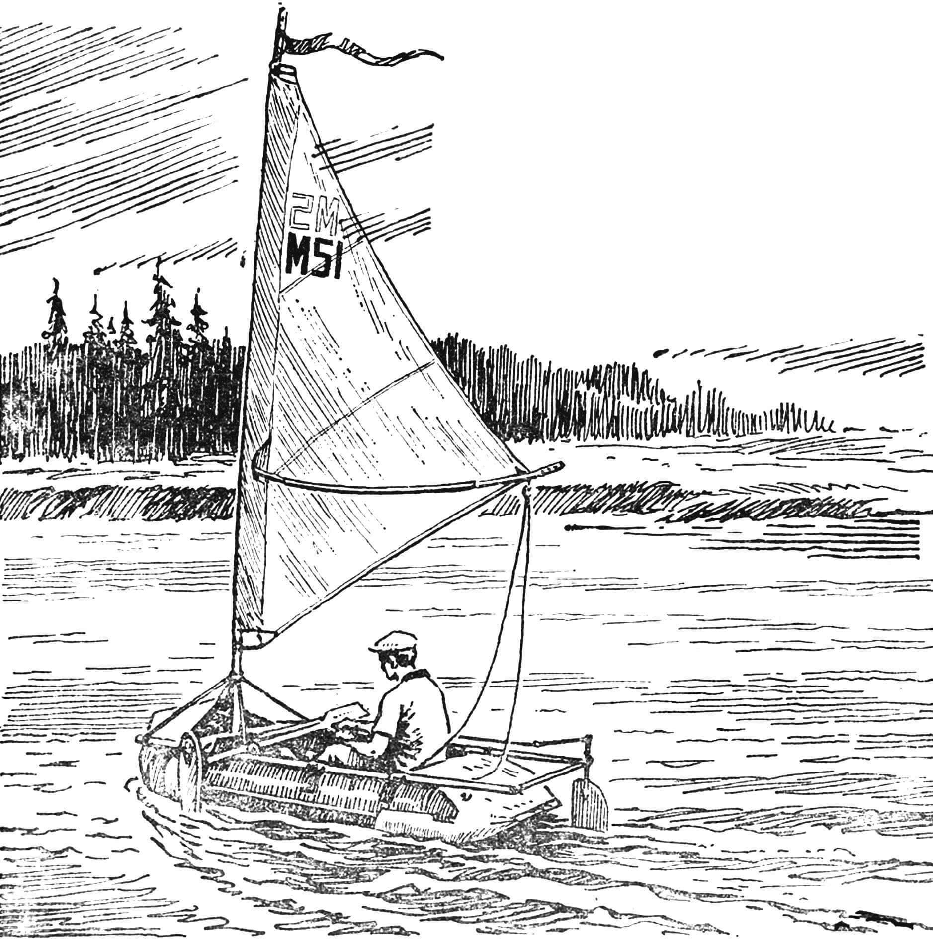
The “Volna” inflatable boat, popular among water recreation enthusiasts, can be easily converted into a real sailing dinghy. The drawings of the universal sailing rig published in this issue, which was awarded a 1st degree diploma at the IV competition of the best sailing and tourist vessels, can be used for any “inflatable boats” and small catamarans.
The boat is armed with only one sail – the mainsail. Such weapons (“cat”) are the most aerodynamically efficient and easy to learn.
The loads from the sail, rudder, fender and tilting helmsman in an inflatable boat are taken on by a tubular power frame. It consists of two longitudinal and two transverse beams – submast and stern. In the middle, the lower part of the mast cup is fixed first, into which the mast is freely inserted. The position of the top of the glass is determined by four spacers going to the longitudinal beams. The frame is attached to the hull using six wide hinges glued to the side cylinders.
The material for the manufacture of the frame is duralumin pipes made of D16T alloy.
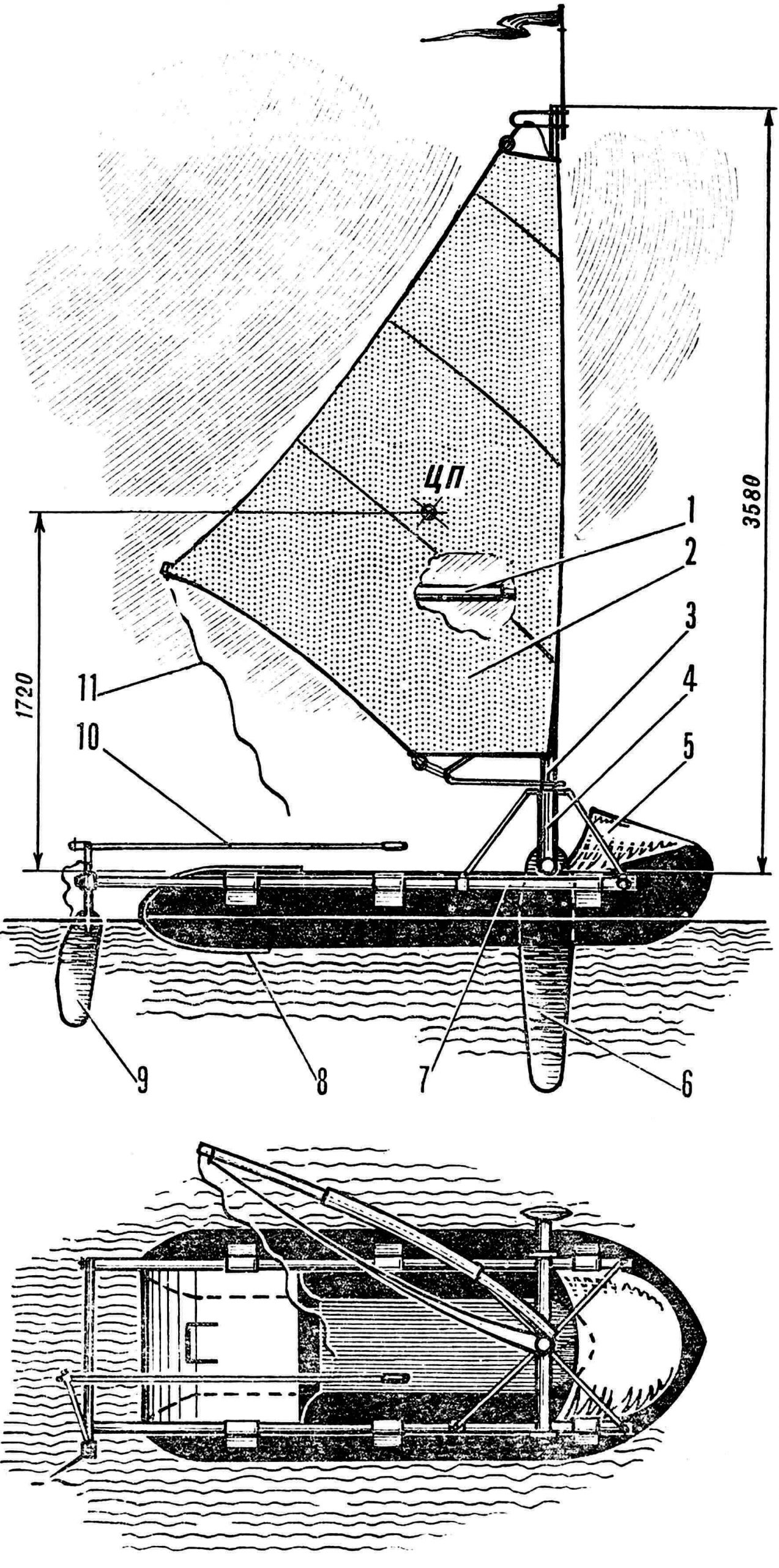
1 – boom, 2 – double-layer sail of the Swift type S = 3.2 m2, 3 – mast, 4 – mast glass, 5 – bow visor, 6 – shverts, 7 – frame, 8 – false bottom, 9 – rudder, 10 — tiller extension, 11 — sheet.
The shverz is hinged at the left end of the sub-mast beam, and the rudder is at the right end of the stern cross member. With such a “diagonal” arrangement, the general center of lateral resistance of the vessel is located in the area of its longitudinal axis and at the required distance from the mast. This achieves good sail alignment of the boat. A certain tendency to bring the nose to the wind on all courses is easily compensated by deflecting the feather at a small angle. To ensure confident handling of the boat, the steering wheel has a large area. It is manipulated using the tiller extension, moving it along the boat, so the helmsman can be anywhere in the cockpit.
The rudder blade is cut from sheet duralumin 4 mm thick. Its front edge is smoothly rounded, and the back edge is ground almost to the tip at an angle of about 20°. It lowers into the working position under its own weight, and rises upward with a sock made of nylon cable. When hitting an underwater obstacle, the pen automatically folds back.
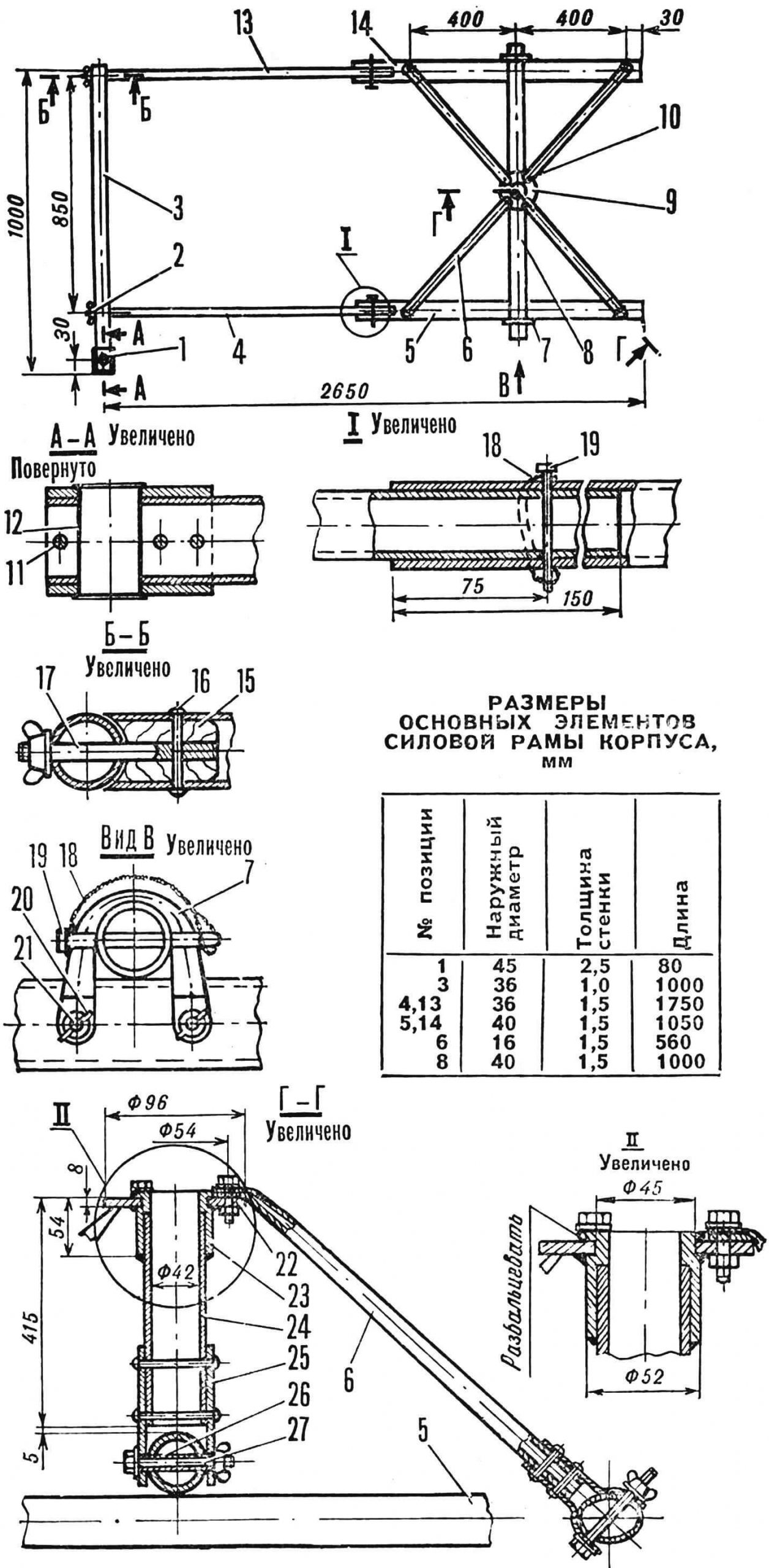
1 – bushing, 2 – wing nut M8, 3 – stern transverse beam, 4, 5 – pipes of the right longitudinal beam, 6 – spacer, 7 – shackle for fastening the sub-mast beam, 8 – sub-mast beam, 9 – mast cup assembly, 10 – spacer mounting bolt, 11 — rivet Ø 5 mm, 12 — steering wheel stock bushing, 13, 14 — pipes of the left longitudinal beam, 15 — cork, oak, 16 — rivet Ø 4 mm, 17 — pin М8Х80 mm, 18 — rubber ring, 19 – clamp, nail Ø 5 mm, 20 – wing nut M6, 21 – bolt M6, 22 – flange, steel, 23 – upper bushing of the mast cup, steel, 24 – mast cup, 25 – plate, duralumin 2.5 mm thick , 26 — spacer, 27 — M8 bolt.
The door is made from pine or spruce boards 25 mm thick. Its shape is symmetrical, with maximum thickness located at a distance of 40% of the width from the leading edge. As you approach the trailing edge, the curvature of the section gradually decreases. The cleanliness of the surface and the smoothness of the sections, especially in the area of the leading edge, largely determine the quality of the work of the drill. The workpiece is carefully sanded and varnished, covering it with 5-8 layers of waterproof varnish. After each layer has completely dried, the shvert is additionally treated with fine sandpaper and ground chalk or tooth powder is rubbed into it.
The swertz is used only when moving in sharp courses or when moving across the wind. It is lowered and raised manually. It is fixed in the upper and lower positions due to frictional force, which can be adjusted by changing the tightening of the bolts.
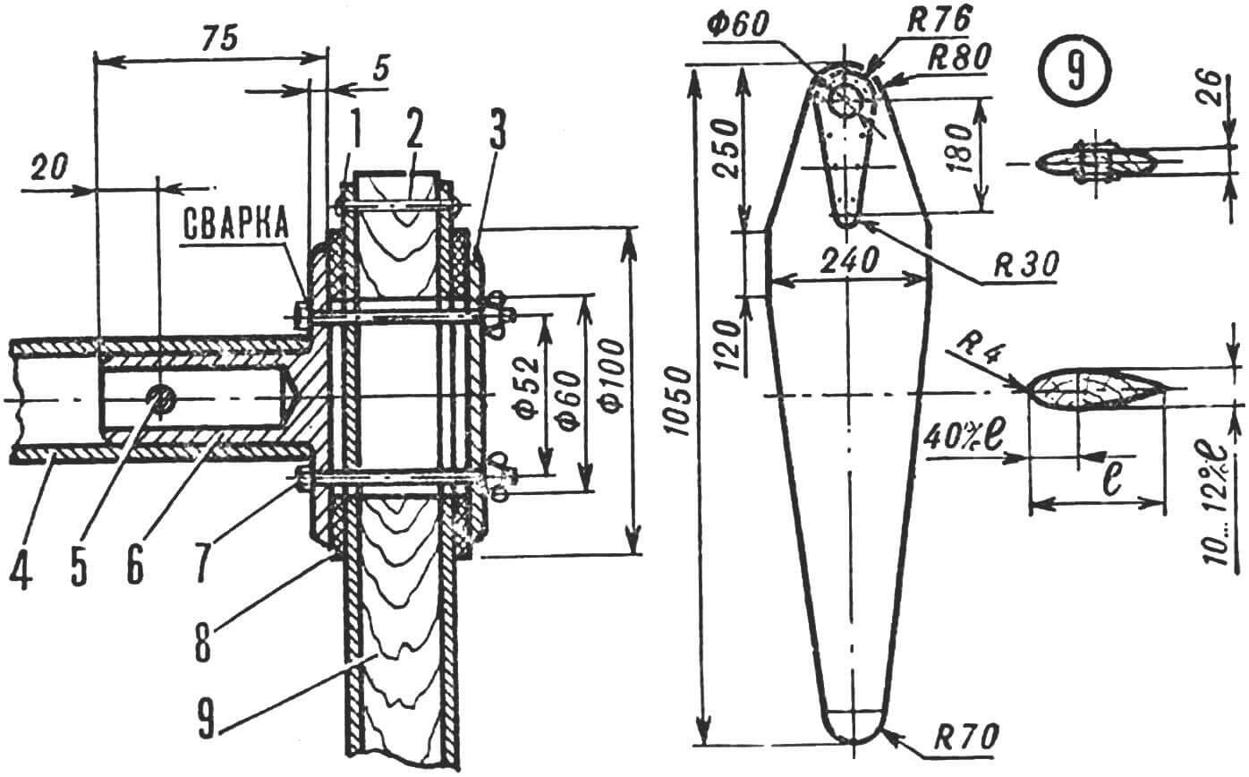
1 – reinforcing plate, duralumin plate 1.5 mm thick, 2 – rivet Ø 4 mm, 3 – cover, duralumin 4 mm thick, 4 – sub-mast beam, 5 – M6 bolt, 6 – hub hub, 7 – M6 bolt with wing nut, 6 pcs., 8 – washer, fluoroplastic 4 mm thick, 9 – screw.
When installing the rudder and centerpiece assemblies, it is very important to ensure their rigidity and the absence of play, otherwise the drag of the dinghy may increase sharply, and it will not go against the wind.
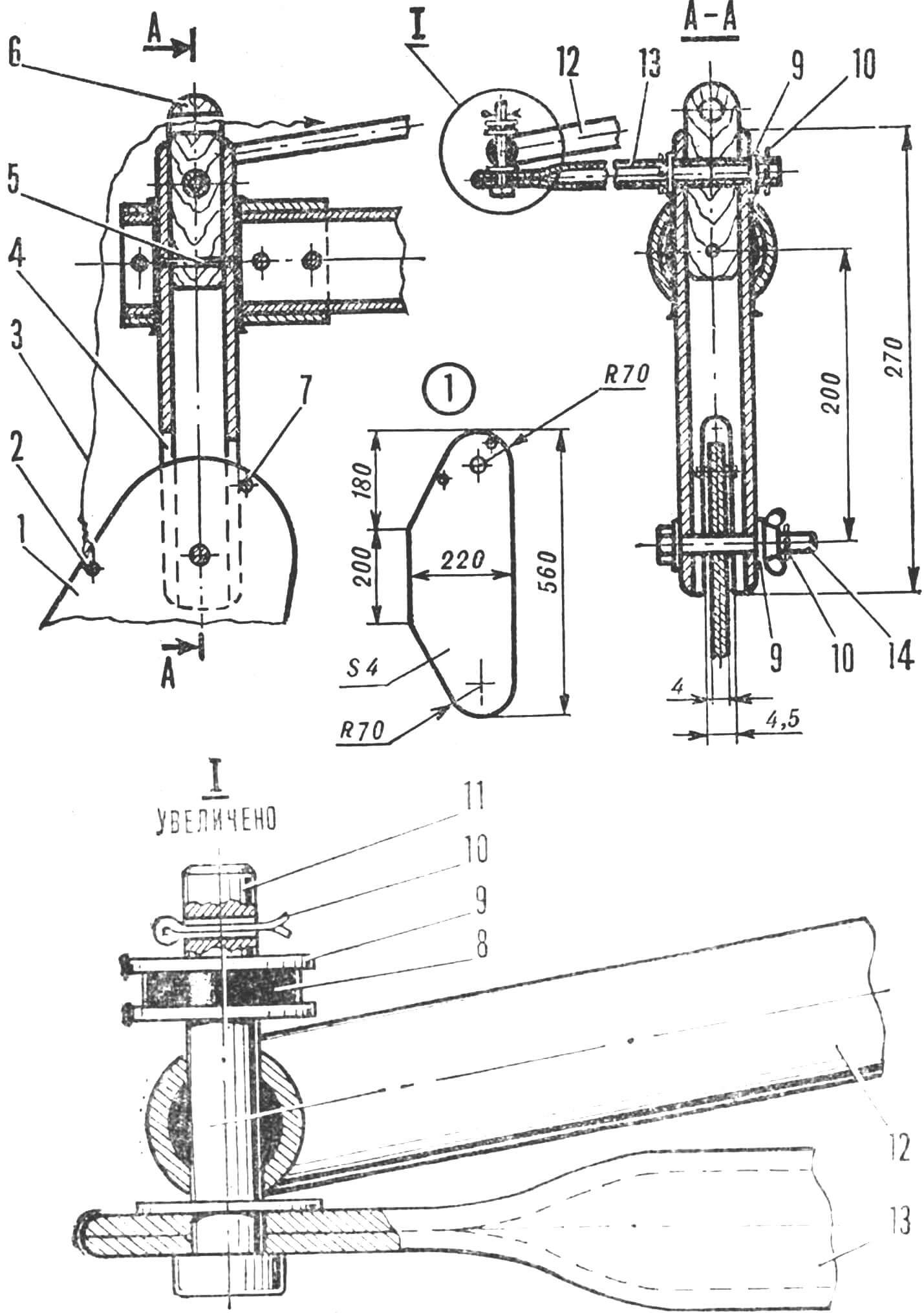
1 — rudder blade, 2 — hole for fastening the wedge, 3 — wedge, 4 — rudder stock, duralumin tube 0 35X3 mm, 5 — rivet Ø 3 mm, 6 — cork, oak, 7 — rudder rotation limiter, rivet Ø 5 mm, 8 — washer, rubber 3 mm thick, 9 — washers, steel, 10 — adjustable pins Ø 3 mm, 11 — pin, Ø 6 mm, 12 — tiller extension, pipe Ø 16 mm, length 1500 mm, 13 — tiller , pipe Ø 16 mm, length 300 mm, 14 – bolt and wing nut M8.
The mast with the sail can make a complete rotation around its axis. This is an important element of ensuring safe navigation during unexpected squalls from any direction or in other situations when the helmsman feels that he is losing control of the boat; he just needs to release the sheet so that the sail itself turns into a weathervane position.
The mast is assembled from two elements. The lower bend – a pipe that can withstand a bending moment of at least 55 kgf*m, in the step area is additionally strengthened with an insert – a pipe Ø 36X1.5 mm, 800 mm long. The mast is completed by an upper elbow made of the same pipe, 1800 mm long. It is inserted into the hole of the lower knee until it stops at the limiter – a Ø 5 mm pin.
The boom consists of three elements – two outer sections made of straight pipes Ø 32X1, and a middle section curved in a horizontal plane. The bend is necessary so that the sail, which has a curved wing shape, does not rest on the boom on one of the tacks (in this case, on the left tack). The boom sections are connected by quick-release pin clamps with rubber rings. A sheet, which controls the sail, and a two-pulley block for adjusting the belly (bulge) of the sail are attached to the nock. The heel of the boom fits onto a horizontal bolt welded to a steel sleeve that slides freely along the mast.
Let’s take a closer look at making a sail. It is known from theory that the smaller its absolute dimensions and the ratio of the sail area to the area of parasitic drag of the hull and crew of the yacht, the stronger the dependence of the tacking qualities of the yacht on the quality of the sail – the magnitude of the pulling force it develops and its ratio to the drag force . The sail of an inflatable boat should be even more advanced than that of large yachts – its characteristics should be close to a rigid aerodynamic wing.
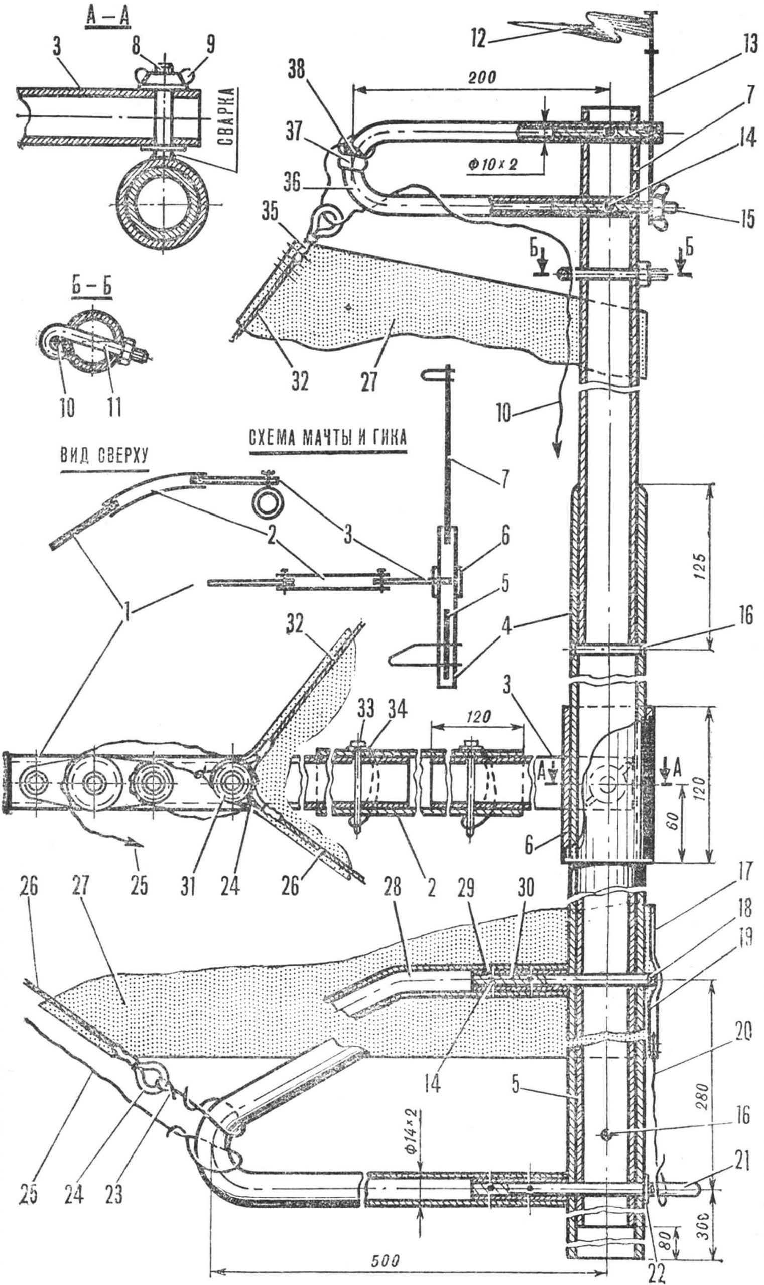
1, 2, 3 – boom sections, 4 – lower bend of the mast, 5 – reinforcing liner, 6 – boom bushing, 7 – upper bend of the mast, 8 – boom axis, steel rod Ø 10 mm, 9 – wing nut M10, 10 – halyard, 11 — hook — halyard block, 12 — weather vane, nylon tape, 13 — weather vane rod, steel Ø 2 mm, 14 — rivet Ø 2.5 mm, 15 — liner, steel Ø 6×50 mm, 16 — rivet Ø 5 mm, 17 — luff of the sail, 18 — cotter pin, 19 — reinforcing pad for the luff of the sail, 20 — tack line, 21 — liner, steel Ø 10×120 mm, 22 — washer, 23 — tackle for adjusting the length of the luff bowline , 24 — luff bowline, copper tube, 25 — sail belly adjustment tackle, 26 — luff bowline, steel cable Ø 2 mm, 27 — sail panel, 28 — lower bow, 29 — bushing, 30 — liner, 31 — clew block of the sail, 32 — luff bowline, 33 — clamp Ø 5 mm, 34 — rubber ring, 35 — cable embedding in a copper tube, 36 — upper bow, 37 — basting (insulating tape), 38 — root end of the halyard hoist.
Of the modern sails with increased rigidity and efficiency, the two-layer “Strizh” type was chosen. It works well and is the easiest to make and operate.
The sail consists of a closed autonomous triangular power frame, which has sufficient rigidity, and a canvas resting on it, which does not carry significant loads. The frame is formed by a mast, bent within the limits of its elastic deformations, bowline cables of the luff and luff, which are connected at the clew of the sail, and a boom spreader.
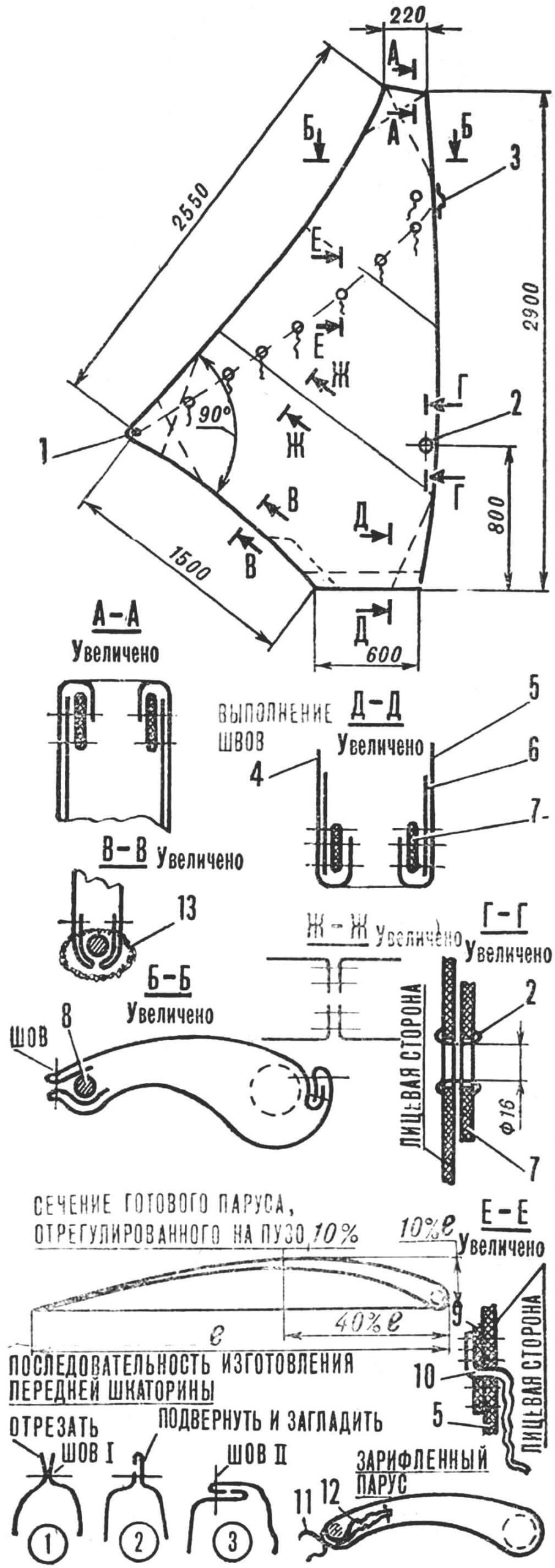
1 — clew eyelet, 2 — eyelet for the passage of the boom axis, 3 — loop for the upper reef pin, 4 — left sail panel, 5 — right sail panel, 6 — bow, 7 — grosgrain ribbon, 8 — luff bowline , 9 – reef bow, 10 – reef tie, 11 – reef tie, tied with a reef knot, 12 – retracted part of the sail, 13 – hand stitch.
Experience shows that a high-quality two-layer sail is much easier to make than a sail with a mast fairing pocket or with a lycrope included in the mast lycgroove. At the same time, it is the most aerodynamically perfect. It is possible to place a mast in the space between the panels, and it does not have any harmful effect on the operation of the sail. All seams, bows and reinforcing linings are inside, the outer sides of the sail remain smooth.
When turning an “inflatable boat” into a sailing dinghy, it’s worth working on its hull. First of all, you need to make a nose visor – definitely! Otherwise the boat will flood. During a hike, the bow section is loaded with bulky but light items.
1 — longitudinal frame element, 2 — hinge, 3 — gluing, 4 — side cylinder.
The performance of the boat will increase if its bottom is extended to the aft ends of the cylinders. An additional bottom can be made from any rubberized fabric; Pharmacy children’s oilcloth in two layers is also suitable. In the above-water part it is glued to the transverse and side cylinders. To access the resulting aft waterproof trunk, a valve is made with two “zippers”.
It is better to sit in a boat on an inflated inflatable cushion. It will allow the helmsman’s weight to be distributed more evenly on the bottom, which does not bend or distort the contours of the hull.
In calm weather, it is more convenient to row with kayak-type oars. To do this, you can use a shortened kayak oar or make one from the standard Wave oars, connecting them using a piece of duralumin tube.
MANUFACTURING A DOUBLE-LAYER SAIL “SWIFT”
Sails of the “Swift” type are sewn not according to theoretical drawings, but locally, directly on the spar. Taking into account waste, you will need about 8 m2 of fabric: raincoat, raincoat or the best types of teak. The stronger and denser the fabric, the higher the quality of the “wing”.
The order of work is as follows.
After making the sail frame with all the adjustments and checking its performance, the dimensions of the future sail are determined in the zero belly position – with the mast at its maximum bend. Based on the obtained dimensions, a drawing of its workpiece is made, seam lines are drawn on it, taking into account allowances.
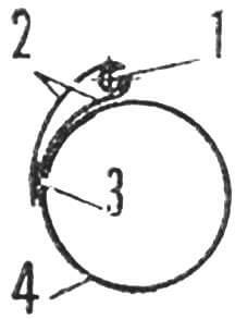
Then the smoothed fabric is spread on the floor and lines of seams and cuts are drawn on it with a ballpoint pen. The tape along the base must be cut off and the edges coated with BF-6 glue. The panels are temporarily connected with rubber glue and sewn exactly in a straight line using the seam shown in the figure – it tightens the sail less than others.
Boots are sewn on all corners of two identical panels of the sail, the ends of the luffs are reinforced with a wide grosgrain ribbon, and metal eyelets are sewn or pressed into the clew corners. Fold and smooth the material along the back and lower luffs. The sail panels along them are pre-sewn using a machine basting stitch. In this case, the top thread is loosened enough so that the seam does not tighten.
The sail blank should be completely flat.
Next stage. The horizontal frame of the sail is placed in the middle belly position – 7% and the sail blank is put on it. The panels are fastened with needles. It is better to sweep the sail with medium-length needles. First, they are pinned every half meter, and at the end of sweeping, the step is increased to several centimeters. By walking around the perimeter of the sail and changing the position of the needles, they ensure that the curvature of the sail’s belly is 7% and smoothly decreases towards the luff.
After the soursop sail with a medium belly has been given the desired shape, set the position of the zero belly and again, by adjusting the position of the needles, ensure that the workpiece becomes smooth and flat. The same adjustment ensures the shape in the position of maximum belly (15%).
Having replaced all the needles on the removed sail with machine basting seams, they put it back on the spar, check the shape for all belly sizes and make the necessary adjustments.
A line for the position of the lower luff is drawn on the right and left sides. By piercing the sail with a needle, marks are placed on both sides to fix the relative position of the panels. Having freed the spar, unravel the basting stitch of the luff. The luff is sewn together cleanly, and a strong braid is sewn to it from the inside, which will support the boom bushing in the working position.
After the final check of the shape of the sail, the luffs are shaped and the basting seams are replaced with permanent ones. It is better not to sew the panels along the lower luff, but fasten them with strong threads every 5 cm. Reinforcing strips of grosgrain ribbon are sewn along the top and bottom ends.
The sail is placed on a horizontal spar in the zero belly position, moistened generously and allowed to dry. Thanks to this operation, all small wrinkles will disappear, redistribution and equalization of stress in the canvas will occur. (In field conditions, it must be wetted after each sailing day and left overnight on the spar in a horizontal position.) To bring the sail into working condition, it is enough to adjust the tackle to adjust the belly.
V. PEREGUDOV
Recommend to read
 WITHOUT LEAKAGE
Pumping a Bicycle tire pump regular takes often more time than similar work at the motorist. The main reason is air leakage through the connecting rubber tubing to the pump and the... RELIABLE CONTACT
About how important proper contact of battery terminals, know of any motorist. But sometimes around the lead pin of the battery cracks, through which the electrolyte or its fumes get to...
