Diagram of the forces acting on the mechanical system speed sudomodel — cord thread.
Designations:
R — gravity model, Q — gravity cords, T — force of thrust of the propeller, R is the resistance of the model, Rl is the resultant of the distributed forces of resistance cords and bridles, N — lifting force model, GC — the centrifugal force of inertia of the model, FC is the resultant distributed according to a linear law of centrifugal inertial forces of the elements, cords and bridles, attached to 2 /3 of the radius of motion of the model.
In the ideal case, the model must have positive lift when gliding and pressing — in a clean flight. To that and should strive in the design of sports aerolizer. Big help tell part analysis the functional purpose of each part, the node and element, only then can you begin to find the optimal design and technology.
Start system model using rubber bands.
Body. Its volume and the external surface of the compress to the limit, allowing only a minimum required buoyancy model. So even before you design need to plan a lot of speed and during construction to strictly adhere to the selected values. To reduce the external (“wetted”) surface, aerodynamic resistance and noise, it is advisable to make a cross-section of the body round the entire length with the exception of the area of the front of the redan. To reduce air turbulence behind the redan, the transition to the body is closed by a fairing with a streamlined contours. Then virtually without increasing midleware section control for the growth of the nose, which will facilitate the transfer of the center of gravity of the machine forward and appropriate improvement of longitudinal dynamic stability.
In the presented model the body is made by known technologies — “winding” cone four-layer pipe. Its internal and external sides of the aluminum foil thickness of 0.03 mm, in the mid — balsa veneer and carbon. Pipe going based on epoxy resin K-153. With minimal weight, this design allows to obtain significant strength and stiffness, while the sharp difference of the mechanical characteristics of the individual layers of the hull will increase the attenuation of the vibrations and will help the jamming noise.
Engine mount are also compressed to the minimum. Had to abandon the traditional lugs of the crankcase and secure it on the hood-Motorama with special pads on the back and the nose of the crankcase. Engine mount magnesium alloy cropped to the limit, the majority is concentrated on the motor, which creates favorable conditions for the operation of the engine.
Fuel tank — single chamber “drinker”; to reduce vibration and the foam is separated from the motor and fixed to the nacelle on an elastic mobile guides.
The nacelle is made of medium density balsa and basswood, covered with glass fiber epoxy resin. Inside is pasted a guide for resonance of the exhaust pipe, the end of which the thread is drawn silencer. The guide serves as both a “reinforcement” for the nacelle. This technique helps to reduce vibration and noise, distributed walls in the atmosphere.
The nacelle is mounted on the pole at an angle lower right side. This gives the following advantages: reduced interference resistance (the angles mate with the nacelle pylon becomes greater than 90°), shortened the outer part of the pylon, the streamlined air flow, the hole of the jet engine is offset from the center of the circle (and thus creates a space for adjusting the position of tank) decreases the vibration level and consequently the resistance of the bridle and cords (partly reduces the intensity of the transverse oscillations are converted into the transverse-longitudinal), it is possible to replace the candle head without removing the engine.
Pylon carved from solid balsa and glued on both sides platinu and plywood with a thickness of 1 mm with mutually perpendicular direction of fibers. So it is possible to achieve high torsional rigidity with minimum weight details. It is important to choose the right place gluing the pylon to the nacelle. It is desirable that the major axis of the moment of inertia of the pylon passes through the center of mass of the nacelle — then the centrifugal load from the nacelle will not give torsional effort.
Traverse one-sided. It is much reduced in size and actually only performs the role of “float” that hold the tail part of the model at the Plaza in a static position. This is due to the use of the ring of the propeller; in addition to increasing the efficiency of the propeller and reducing the noise, the nozzle has a significant stabilizing effect. Simultaneously with the decrease of the resistance of the small cross member decreases interference resistance pairing unilateral cross member with the body. Traverse is at an angle to the horizontal plane. Due to this, in static position model leans to the right, relative to the centre of buoyancy and shifting the center of gravity. This ensures reliable balance afloat. In dynamics due to the tension cords high-speed becomes “even-keel”, traverse float completely off the water. The material of the cross member — aluminum foil of 0.3 mm thickness.
It should be noted that the spacing of the masses along the length of the housing increases the moment of inertia of the model relative to the transverse axis, reduces the influence of external disturbances.
The bridle is attached at the ends of the titanium bracket, ring and nozzle traverse. Relatively large shoulders of these points relative to the axis of cord models and their spacing in the vertical direction serve to the benefit of lateral stability in motion. Travers is attached together with the head fairing. Rubber rings introduced in this connection, vibroisolated individual elements. With all other things such connector allows you to easily replace parts of the tail section, to conduct experiments with traverses different profile depending on the condition of waters and other external disturbances.
In the end, a few words about the start. To avoid bad shots and be able to start with aerodynamically heavier screws, giving a small thrust in place, used “start with the tires”, similar to class A. However, class B1 hook for rubber bands should be put in the center of the center of gravity of the model. Only then can the tension “catapult” will not create a moment about the center of mass of the device, and it will easily and with great reliability to start. The place fixing the second fixed end of the rubber is chosen so that at the initial moment of movement of the tape was made with the axis of the model a certain angle and were not included in the process of acceleration in a rotating propeller (when using a ring nozzle that danger disappears). As acceleration mentioned angle increases with a simultaneous decrease in tension of the rubber. Thus, the model reported an initial speed at a constant stretch cords.
SHAHAZIZYAN G., candidate of technical Sciences, master of sports of international class, Yerevan
Recommend to read ECONOMICAL PENCIL When the hand is not a pencil of suitable color or hardness. would be useful and "bits", but they are inconvenient to use, they can be extended by sticking in a metal or plastic tube of... TUBE OPPOSITE As you know, the tube is required to ensure that the contents of the bottle could not to spill out. Well, if the cork of champagne with a hot needle to make two dozen holes with a... 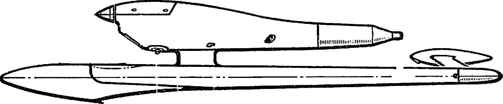
 Two world records set at international competitions in ship modeling Soviet athlete, master of sports of international class G. shahazizyan. It happened at the starts in the Bulgarian city of Tolbukhin, one of the records was blocked in the B1 class the previous results from 24 km/h! The event is really unique — even a fraction of a percent increase of speed required for approval of the record, are designers and athletes at the cost of tremendous exertion.