 Today, when in any toy store you can always find a not too expensive radio-controlled models of cars, their availability would have to completely replace trace model. However, practice shows that the latter is still very popular in the children’s centers of technical creativity with circuits. There is still continuing work on creating a new highway model. The fact that they remain a very fertile subject to technical creativity, as you can make them without complex machinery and without expensive materials and components.
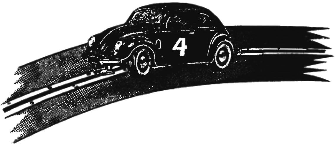
A homemade prototype of the proposed trace model became the famous Volkswagen beetle, the form of which is best suited for the manufacture of such copies.
A little about the creation of the prototype and its design. The machine was developed in the years 1934-1936 famous avtokonstruktor by Ferdinand Porsche. The main concept was: carrying lightweight 4-seater body, fully independent suspension, the rear engine and rear wheel drive.
A successful run of prototypes with a length of 50 000 km showed the reliability of the vehicle. The state has allocated for the organization of its production of about 30 million marks, and in may 1938 in Wolfsburg began to build at the time the giant plant. However, the outbreak in September 1939 the Second world war Prevented to deploy the serial production of the small car plant switched to production of military transport equipment.

VW beetle prototype trace models

Chassis trace model:
1 — bandages of fastening of the brushes of the current collector (copper wire); 2— holder assemblies (PCB); a 3.15—mount housing of the current collector to the frame (bolt with nut M3 and washer); 4,9— brackets front and rear axles (tinplate s0,5); 5,10— bushings-bearings front and rear axles (bronze or brass); 6,8— front and rear electric motors (DC-5-19); 7 — frame (steel, wire EOD Ø2,5); 11,12 — frame front and rear electric motors (tinplate s0,5); 13 — decorative wheel cover (aluminum); 14 — bushing (aluminum); of 16.21 — mounting wheels (nuts M2,5); 17 — track (PCB); 18 — brush of the current collector (copper braid coaxial television cable); 19—tyre wheels (porous rubber); 20 — wheel hub (aluminum); 22,24 — primary gear drives; 23 — tying a copper wire, followed by propanol; 25,29 — shafts front and rear (steel, wire EOD Ø2. 5); of 26.30 — disc gear drives
After the war, in late 1945, on the initiative of the British occupying authorities, the plant received the state order for the edition of “Zhukov”, and in 1947, have been deployed to mass-produce them. In Germany, the “beetles” was produced until 1972, only the factory in Wolfsburg made more than 15 million of these machines (along with foreign affiliates were fired 21 million copies).
Design solution of the appearance of subcompact and today is not in conflict with the appearance of modern cars. Volumes, boldly decided to form a smooth but fairly complex surfaces, collected into one harmonious whole..
Located in the rear of the engine is allowed to visually lighten the front of the car, and the hood with a very distinctive podshtampovki gently “stack” to the front bumper. A good body shape in which delicately paired straight and curved lines, consolidating into a unified whole all the other elements, and from which nothing removed, is this harmony, apparently, was the “pass to the future” car, won more than 20 million customers.
As the power unit used the original boxer 4-cylinder engine working volume of 1,285 liters and 40 HP; the location of its rear predetermined basically a diagram of the undercarriage.
Front suspension independent trailing arms with transverse torsion bars, telescopic shock absorbers and stabilizer bar. Rear independent, double trailing arms, transverse torsion bars with telescopic shock absorbers and stabilizer bar.
The instrument panel of the car at first was not: before the driver was located in the glove box and speedo. The only warning light (flasher) mounted in the handle of the switch of turns.
Subcompact car Volkswagen “beetle” is often used by tracks as a prototype for the body characteristic and recognizable forms; such a case it is easy to applied to the wall of epoxy resin and thin fiberglass on the disc or in the matrix or to the vacuum-formed from polystyrene or plexiglass.
If you intend to create several models of the hull makes sense for them to glue in the matrix. To begin to make a master model of drevesiny, foam or even paraffin.
Well-established, carefully sanded and coated with a separating layer of the master model is manufactured matrix. To make it from plaster or compositions from epoxy resins and filler — dry fine sand. Note that the matrix for gluing the body should have a connector at the plane of symmetry, otherwise the finished shell cannot be extracted from the matrix.
Finished volumetric and joined to the inner surface of the resulting shape is applied to the separation layer mastic parquet wax or car Polish to wax-based (e.g., “Superfos”), then the matrix is carefully polished. For shell it takes three or four layers of fiberglass, each layer is carefully lapped to the surface of the matrix.
After curing the binder matrix is parsed, it is extracted and refined by shell: it cut the wheel openings, Windows, holes for headlight and tail lights.
Frame model is assembled from steel wire grade optical fiber with a diameter of 2.5 mm. the Design is simple: a single butt wrapped in thin copper wire and carefully probivaetsya. Brackets front and rear axles are cut from tinplate, 0.5 mm thick and soldered to the frame by soldering fixed on the brackets and bushings-bearings, which rotate the axis.
The body of the current collector Teflon, brushes of a screen braid of the antenna cable mounted on it with a strap of thin copper wire with subsequent propanol.
The wire frame has minimal torsional stiffness and, in the role of the suspension, ensures a constant contact of all four wheels with the track.
The power plant is a twin-engine, consists of two well-known automodellista engines of DK-5-19 mounted on the frame is soldered to the lodgment of tinplate with a thickness of 0.5 mm. While each of the motors with a gear causes the rotation of its two wheels. In addition to doubling capacity, this drive provides and the increased stability of the car on the track, typical of all-wheel-drive vehicles — it is especially noticeable when passing the model of steep turns and sharp accelerations and decelerations on the straights.
Gear transmissions have the gear ratio i = 5. Each of them consists of a cylindrical gear on the motor shaft and disc gear wheel on the shaft of the wheels.
Shafts front and rear axles — wire grade optical fiber with a diameter of 2.5 mm. At their ends tapped M2,5 for mounting the wheels two nuts. Disc gear wheels fixed on the shafts by brazing.
Wheel models have turned from D16T wheels and tires from porous rubber. The latter must be secured to the wheels with glue of type “Moment”. Decorative caps are machined from duralumin, and the outer surface is carefully polished.

A simple training track

Cross-section training tracks:
1 — cross member (wood, brick 30×30); 2,9— side tracks (plywood s5); 3 — the screw 4×30 head “itotal”); 4 section of the route (s10 plywood… 12); 5 — route model; 6 — mount contact of the tyre (screw 3×10); 7— pin bus (copper strip 6×2); 8 — track (linoleum)
As already mentioned, the model is designed for racing on a special track, and make little micro-car racing makes sense only if the access Modeler to it. However, a simple training track can be build in almost any circle. This will require some sheets of 10 – or 12-mm plywood, copper bus-bar section 6×2 for the contact network, the linoleum and wood blocks section of 30×30 and 50×50 mm.
The simplest route — “eight” – crossing paths in one level. It can be made extremely short, directly connecting two tracks-circles or long, adding to the semi-straights. However, to compete at a track will have turns, timing with the passage of a predetermined number of laps.
Straight sections are assembled from sections, consisting of arranged parallel to separate the plywood strips with a width of 70 mm with a 5 mm gap between them. Strips are joined into a single roadway cross — wooden bruski section 30×30 mm.
The curved section of the track makes sense to cut it out with the help of a special device comprised of a jigsaw mounted on the end of a flat Board; a second Board hinged end (bolt and nut) is fixed on the table. It is a kind of a huge compass with a jigsaw instead of a pencil, which allows to move the tool strictly on the circumference. In this device a circular track elements can be done without a preliminary marking are exactly the same — are easy to stitch.
On the ready track with screws-head “wpoty” mounted tires contact network, and then the roadbed glued linoleum.
Further, if desired, the track can be more difficult, adding upon the outer side another track and organizing the crossing of the straight sections in two levels.
I. SOROKIN


