 Rocket 8К65 – single-stage, liquid-propellant rocket engine and with load-bearing fuel tanks. As propellants were first used hypergolic in contact with nitric acid (AK-27AND oxidizer) and unsymmetrical dimethylhydrazine (UDMH fuel). Flight control is performed by means of gas-jet rudders.
Autonomous inertial control system for the first time in domestic practice used a gyro-stabilized platform with gyros on air suspension. The angles of rotation in three axes are measured by the respective inductive sensors. Also on gyroplatform the sensors linear accelerations in the lateral and normal axes of stabilization, which respond to linear acceleration. In addition, gyroplatform installed the clip with five sensor heads of integrator of speed. The team at engine shutdown takes place after tripping three of them. All this increases the reliability and accuracy of the automatic control range.
The flight of the missile to the target occurs according to the program, which is developed at the turn of gyroplatform stepper motors. Command them to turn gyroplatform (and after it takes place and the missile) are supplied from the pulse generator software operating on a given program. Generator sets and profile of change of speed of the rocket. For reliability work in parallel two blocks. The program is recorded on the film in the form of alternating black and white transverse bands (separately for speed and angle of turn). The tape is pulled through a block of photosensitive sensors. The sensor photodiodes, each black and white pair is converted into an electrical impulse. The passage of one pulse leads to a rotation of the rocket on the corner two minutes or the change of velocity of 4.4 m/s. the Use of a programmable pulse generator is a software Cam mechanisms on earlier samples of the missiles reduced the error of turn of the missile at the target and increased accuracy on the range.
The housing of the tail compartment is made in the form of a thin conical shell of riveted construction formed by the power set and the cladding. The conical shape of the compartment with a large base at the bottom of the slicer allows you to put the engine, shift the center of pressure down the length of the rocket to improve its stabilization in flight. On the outer surface of the housing of the tail compartment with fittings stabilization planes has four trapezoidal console of the aerodynamic stabilizer and made the hatches for access to the aggregates of the main engine. On the end frame fixed launch support, transferring the load from the rocket on the launch table, with gas brackets graphite wheel and electric steering gears.
The rocket is mounted sustainer rocket engine RD-216 (8Д514) developed by OKB-456 under the direction of V. P. Glushko. It is formed of two identical motor units 8Д513, United by a frame for mounting to the housing and having a common start-stop system. Each block of two combustion chambers Pano-welded construction with internal and regenerative cooling, turbopump Assembly (TNA), gas generator working on the main components of the fuel, and the control system. TNA placed between the combustion chambers have critical sections nozzles. Thanks to the General system startup, all cells are included both the engine and thus eliminates the risk of tipping over of the rocket on the launch pad. Rocket engine frame is mounted to the power frame of the tank of fuel.
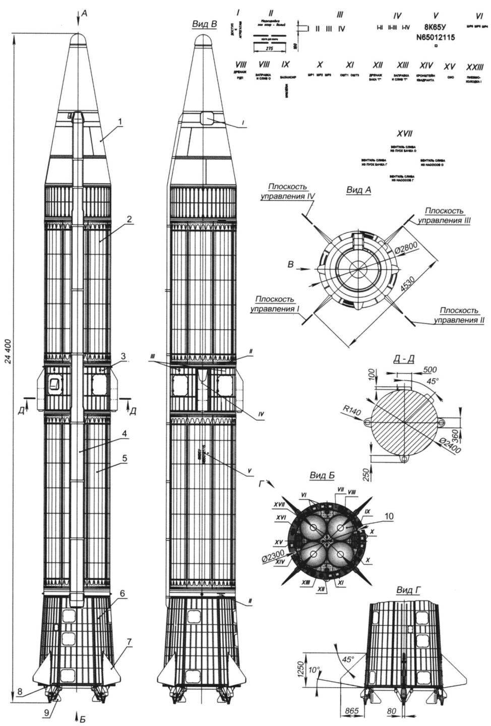
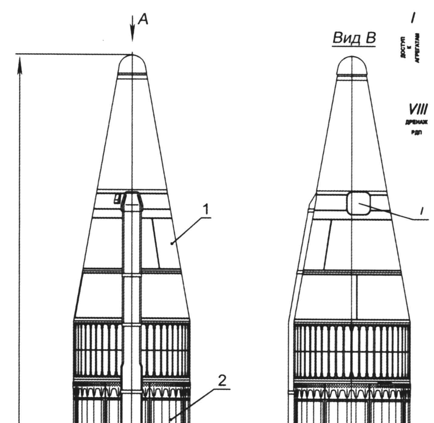
Fig.1. Ballistic missile of average range (index 8К65):
1 – head; 2 – the block oxidizer tanks; 3 – megacool compartment; 4 – gargrot; 5 – fuel tank; 6 – the rear compartment; 7 – aerodynamic stabilizer; 8 – bearing; 9 – gas wheel; 10 – nozzle of the engine
The missile has a detachable in-flight monoblock head part with thermonuclear charge capacity of 1 MT or 2.3. Its separation from the body produced by main signal from the integrator to turn off the engine by breaking the three explosive bolts. Immediately after that includes three powder brake motor mounted outside the instrument compartment. Their action slowed the flight of the rocket and unfolded it to exclude the impact of the housing with head part. Was also provided for the emergency detonation WARHEAD and shutdown of the propulsion system in case of significant deviations of the missile from a predetermined flight path.
8К65 rocket was launched from a ground launching device, consisting of a simple launch pad and the cable mast. Priming and aiming the missiles was carried out after its installation on the launch pad. The designers managed to achieve a higher launch ready for launch, compared to the previously manufactured models of missiles.
It was later developed mine version of the missile – 8К65У. It was built silo launchers (shpu) “Chusovaya”. The modified missile was more advanced than 8К65. It is equipped with a remote control system of the refueling propellant components and compressed gases. Silos have significant advantages over ground starts against protection from damaging factors of nuclear explosion, but also ensured long-term maintenance of missiles ready to launch. Rocket 8К65У has been standardized for above ground and mine starts the track from the mine – free, gas-dynamic, starting from glass, on their own engines.
Rocket 8К65 was used in the cosmic order. At its base was established geophysical rockets (Vertical-3 -Vertikal-12), which had an index К65УП. It was also chosen as the basis for the creation of the carrier rocket light class, significantly exceeding the capabilities of the first version of the WG “Space-2” on the basis of R-12.
Offered today, the model-copy of the R-14 (Fig.2) scale is 1:30. It can be used as sport “shell” to perform at the competition in the category of S7 and as an exhibit at the exhibition. Designer-models – Nikita Belbacha (8th grade student of the Lyceum in Elektrostal).
For making this copy of the basic are made of paper with a thickness of 0.2 – 0.25 mm and lime. Before you start building up, you must make two mandrels. One – cylindrical – dimensions: length of about 350 mm and a diameter of 79 mm. the Other cone (angle – 3 degrees) – for the tail cone. They (bars) can be made of metal or plastic. Metal is desirable to facilitate inside (counterbore hole).
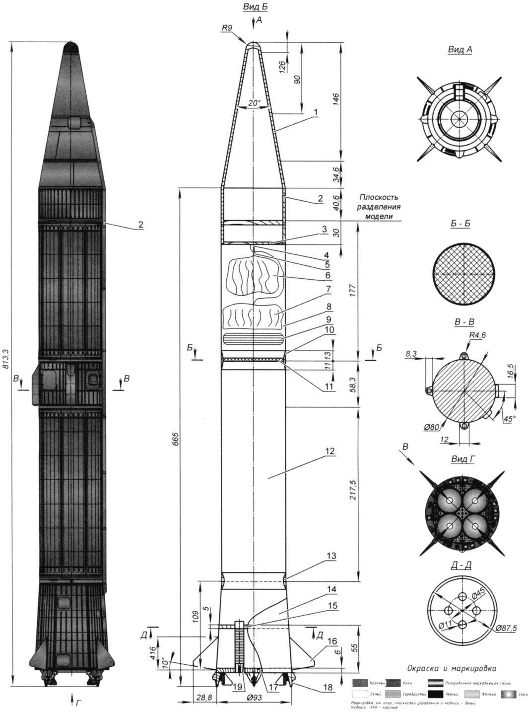
Fig.2. Model-a copy of the R-14:
1 – fairing; 2 – bushing; 3 – cap; 4 – loop suspension; 5 thread to bring a parachute; 6 – parachute head part; 7 – chute of the main body; 8 – the top item housing; 9 – wad; 10 – a connecting sleeve elements of the case; 11 – retaining grille (mesh); 12 – the bottom element of the case; 13 – a connecting bushing for the rear conical part; 14-tail cone; 15-upper frame; 16-aerodynamic stabilizer; 17 lower frame; 18 – MRD; 19 – support
The body length of the cylindrical portion of about 500 mm. to Glue and remove it from the mandrel with a diameter of 79 mm for inexperienced modelers will be difficult. One solution is to make it from two parts (elements). And so it was done.
Each element glued from two layers of drawing paper on the mandrel with a diameter of 79 mm. After drying, the treated workpiece seam with sandpaper and covered with a layer of nitraria. After drying again sand the entire surface with sandpaper – remove the pile.
Then mark out a sharpened pencil the location of the welds and paste over each element of the hull with thin strips of writing paper, making them the sealing of riveted seams gear with step 2 to 2.5 mm. Width strips of paper at the same time – 150 and 199 mm. And it is better to stick with 5 elements – won’t wrinkle, dipped in glue (PVA) paper. After drying, one element mandrel fixed thereto element is placed in a vessel (bucket) with hot water and cover with a plastic bag create a steam bath and kept there the mandrel is about 30 minutes. The paper gets wet and the item is freely removed from the mandrel. The same procedure is done with the second element.
After drying the obtained details of their butt. The top is in two parts with a length of 175 mm and 40 mm bottom 217,5 mm. This operation (trimming) is carried out on a lathe, previously holding the cartridge in a wooden mandrel, and applying the low-speed rotation.
To connect the top and bottom of the hull elements is used the bushing from basswood with a width of 25 mm and a wall thickness of 2 mm. Pre-glued to it holding the bars. It can be run from a large metal grid (cell 5-8 mm) or collect from bamboo slats with a diameter of 3-5 mm.
At the top end (end) of the hull glued sleeve from Linden with a width of 30 mm and a wall thickness of 2.5 mm after assembling the model, it will be inserted fairing.
Tail section vyklevyvajut on the cone mandrel from two layers of drawing paper. After drying, the butt length 109 mm, holding the mandrel in the Chuck of the lathe. Connect the tail section and the body via a bushing. Her first glued in a short piece (tail section), and then into the case. The finished building paste over segments of tissue paper, making them the imitation of riveted and welded seams. For workpieces tail cone must make a template scan, which is one-fourth of the area of the cone. Bottom of the hull glued the motor block. It consists of two base frames, made of plywood and four containers of MRD. On this model the power unit is universal. It has two application engines – four and two, their impulse – 5. I note that the flight height for two MRD will be small – 15 – 20 mm.
Stabilizers (four of them) are made of fiberglass with a thickness 2.5 mm, profiled and are fastened with studs to the motor (power) unit. They give only passing bench evaluation and flight.
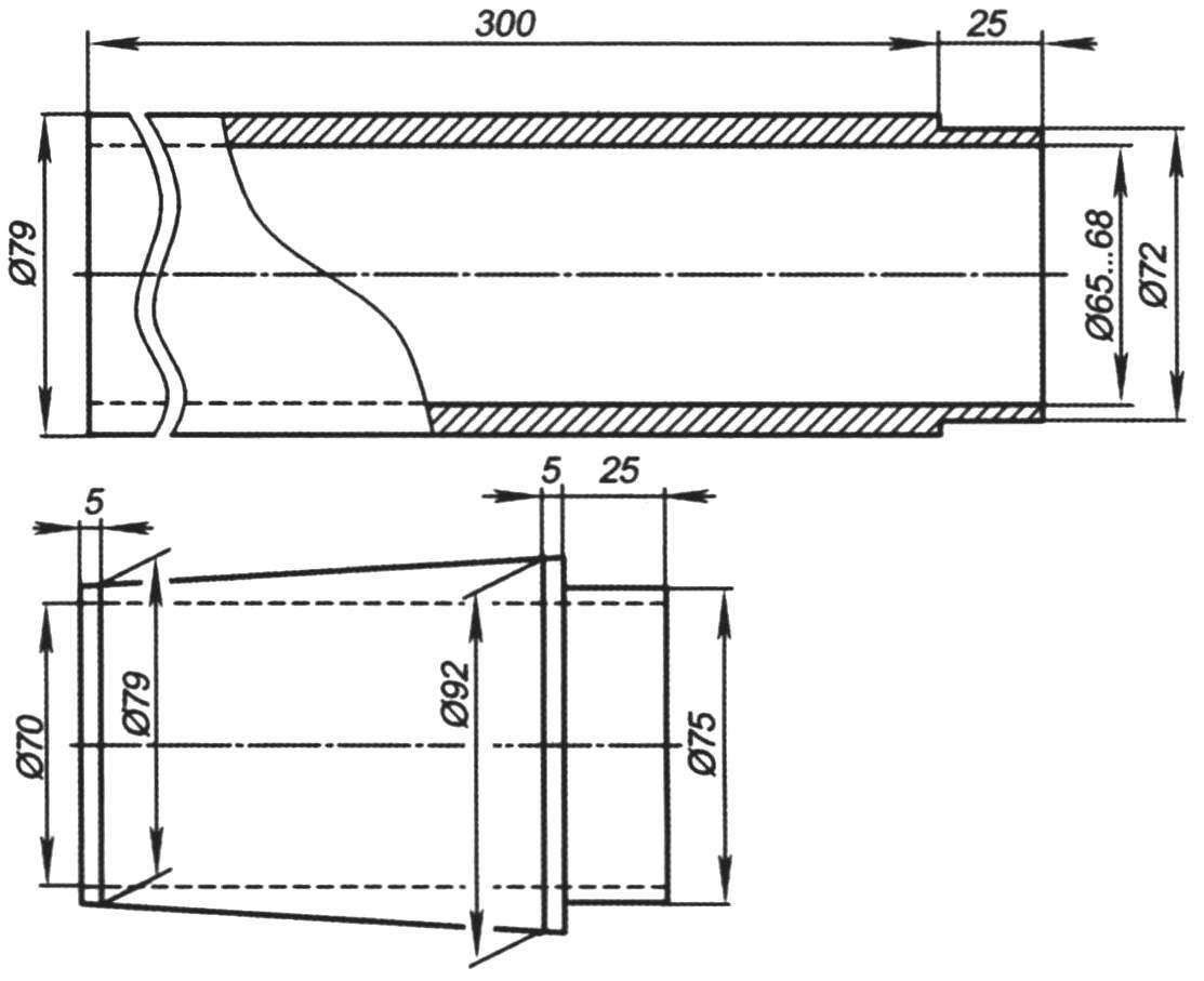
Fig. 3. Mandrel for bonding the elements of the case-models the R-14 (1:30):
I – tail; II – Central
Fairing carved from basswood on a lathe. Billet with a diameter of 86 mm and a length of 200 mm is clamped in the Chuck of the lathe and process from the outside, reducing the diameter to the cartridge. Then gradually rassverlivajut inside to a depth of 150 – 152 mm drills of different diameters from 25 mm to 10 mm and make the internal conical bore (the angle of 22 degrees) long cutter. And to a depth of 32 -33 mm bore – cylindrical (diameter 68 mm).
After that take it out of the Chuck of the lathe, clamp a new billet and make the frame for the fairing and fix it reamed part. The junction (for safety) coat with glue dots. After drying it outside is treated with a cutter, sand paper and coated with nitrocellulose lacquer.
On the lower part of the fairing attach short length of housing length of 40 mm. plywood carved frame with a diameter of 68 mm and tightly inserted into the end of the fairing, pre-vkliw it a loop for attaching a parachute. Then, after loading the fairing when balancing the finished model, it is necessary not to forget to attach the frame tightly.
The final phase of work on the model-copy -registration and bonding of all exterior items: doors, boxes, racks, pads; priming and painting. Main color – khaki (green). To simulate the bottom and nozzles used silver. Nozzle glued on the mandrel from paper in two layers and othertown length of 20 mm.
In the model used two parachutes – for the head part (diameter 450 mm) and main body (with a diameter of 500 mm).
Assembled model with MRD center – find the location of the CG (center of gravity). It needs to be at the junction of upper and lower case elements (about 400 mm from the “top” model).
The starting weight of the model is about 250 g (without MRD).
V. ROZHKOV, Elektrostal, Moscow region.
Recommend to read
 VELOTANDEM “TWO PLUS TWO”
Among the participants of the traditional velometer in the city of šiauliai, this bike stood out primarily for its unusually large capacity. Still, relatively compact and lightweight... SAILBOAT-UNIVERSAL
If you manage to build such menopausic, then you immediately become the owner of a "flotilla"! In fact: craft the proposed design for its small size called the author of "Hummingbird",...
