Horizontal tail:
1 — edge (blank tight grained basswood or light pine 5X5 mm), 2 — ending (lime 2 mm thick), 3 — spacers (Linden or pine 2X3 mm), 4 — Central insert (Linden thickness of 5 mm), 5 — force plate, 6 — joint. Below shows the Elevator, repeating the stabilizer. The rear edge of the steering wheel and the front stabilizer can be performed from Reiki billet 4X4 mm.
Scheme of the Assembly of the rudder:
1 — a pin of fastening of workpieces edges on the stocks, 2 is the workpiece edge, 3 — strut, 4 — insert, 5 — stapel (Linden centrifuged Board).
Bracket control (“hog”):
1 — Elevator, 2 — steel bolt (L=30mm), 3 — Sukhar (PTFE or nylon).
Rocking.
Cables management:
1 — cacalacky tip (steel 0,8 mm Ø), 2 — insert (OVS wire Ø 0.5 mm) 2 — core cable Ø 0,8 mm, 4 — spring-hinge, 5 — lug (wire OVS Ø 0.5 mm), 6 cord, 7 — carbine (OVS wire Ø 0.5 mm) 8 — lock carabiner (plastic tube Ø 2 mm).
* For these sections the connection of winding naked copper wire Ø 0,1 — 0,15 mm and solder POS-30 with soldering acid.
The crutch (the wire OVS Ø 2 mm).
Pull the Elevator control (OBC wire Ø 2 mm).
Manufacturer hinges hinge steering of semi-rigid steel wire Ø 0.8 mm:
1 — pre-bending ring, 2 — crop, 3 — formation of the eyelet, 4 — knurled knurled rod, 5 — degreasing, 6 — protection of fat-free blanks of the plastic tube. Above shows the assembled joint with winding rods with a thin cotton thread.
Knowing the hopelessness of trying to produce alinalove wing, in the new model, projected, stacked, with partial soft lining. Such a plane when the relative thickness of the profile of about 6% (9 mm with a chord of 150 mm) can do exceptionally durable and meet the requirements of mass. Two of the plywood skin of the forehead have a total mass not exceeding 50 g, not more weight, and the rest of the frame.
The main thing that is presented to the Assembly of the wing, the maximum accuracy of adjustment of parts to each other and the use of plasticized epoxy resin has been repeatedly tested on the reference wood samples. The adhesive components are mixed, pre-weighed them on a laboratory balance or to the use of medical syringes. In the latter case, it is better to use two syringes: 10 cm3 under resin and 1-3 cm3 under the hardener; the selection of the optimal ratio of the components of control make a few “batches” of different proportions.
Plywood blanks after adjusting the circuit must be sanded down to remove contaminated areas of the wood, similar to that prepared for the Assembly and rods and net should be not only details, but also the working place, hands. Rib the entire wing with the wingtips the best thing to do is precisely processed by sawing the plate of lime of a wing profile into its individual parts numbered sequentially detachable from the wing-billet rib. Polonaruwa are manufactured separately and are adjusted in place in the assembled frame of the wing, having only the top hard shell.
Assembly sequence is as follows. Based on the exact profile of the wing, prepare Reiki-lining under front and back edges and fix them on a flat Board bench with imposed on it by drawing protected by a transparent Mylar film. Pins attach the lower part of the hard plating is already sticked to the workpiece the front edge, put fins, ribs and trailing edge. After monitoring the connectivity of their parts if necessary podshlifovyvat and again put on the slipway. The rear portion of the plywood sheathing is tight to the bottom of the ribs wooden pegs with wedges and all the seams pour svezhenakleennyh epoxy resin, continuously monitoring the absorption of the binder and its presence in the seams until thickening. Waiting for the complete curing of the binder and removing the wing from the building berth, wall mounted (“spar”), scarves and all controls. Also on the slipway conducted a sweep of the frame under the upper part of the hard plating and gluing. Due to the continuous operation with fixed slipway wing manages to make it completely flat (the forehead is a torsion bar formed by the lining edge and the wall, extremely violent torsional and editing is not amenable), and having a reliable rigid casing in the capture area during the capture of the model on landing.
Before tight Mylar film frame carefully visitvisit average (equalization form) sandpaper, then fine (surface preparation). Ordinary transparent film, the supplied sets for modeling (or at least metallized, coated — inside) and having a thickness not less than 0.025 mm, cut out and degreased the inside with gasoline and acetone. The frame is covered with liquid deluted glue “Moment”. Unfortunately, to recommend for leveling of the adhesive layer is anything other than the fingers, it is not possible — only this “tool” will help evenly distribute the glue and to obtain a result, wherein during the welding film is not formed, no bubbles, no bumps. Of course, before applying the covering the glue completely dried. First fit the lower part of the wing, and then the upper; edges should be “the castle” due to roll film. Do note that during the installation of the wing to the fuselage center section is removed and the tape, and the remnants of the “Moment” on the band width of about 16 mm.
The fuselage is racing to manufacture even easier. The sequence of operation is as follows. First of all assemble the frame, and after the curing process of epoxy glue the tail “on a cone” and glue right side plywood sheathing. Waiting for polymerization of the glue, gently cut the window under the wing and under the engine (to then not look for their exact position) and wpoty stick with low fat screws to secure the motor. The next step is to overlay the left of the plating and Stripping of the fuselage.
Stabilizer — stacked, like the Elevator. At first glance it may seem an odd choice for such a design. But… remember the conversation about the disadvantages of all-wood wings. It would be possible to use the foam option followed by pasting all surfaces fine writing paper. But such a stabilizer would be a few losing weight. And when stacked have a ton of stabilizer, about 13 g together with the cording, with the latter forming only at the edges after painting gives an excellent result — the impression of a smooth, perfectly polished plate.
The Assembly frame is not quite familiar. She is also on the stocks and starts with fixing the edges of the rails of square section, set on edge. Here will help of safety pins stuck through the edge of the berth. Between the fixed edges set customized by length, girth and ending with inserts. After checking all the seams to spill epoxy and put scarves. When the resin is fully cured, the frame is removed from the pile and using the “kurilka” (the flat bar with glued on abrasive paper) is adjusted to the thickness of 4.5—5 mm, and then profile the edges, which from the side of the hinge further prostrogat in the vertical plane.
Completely assembled model painted with the use of sprays or airbrush, and elevators to better decorate before hanging on the model. The hinges of the handlebar mounts can have various design, you can use the one shown in the drawings. Its advantages are ease of gluing, as for mounting on the tail enough to drill the edge hole Ø 1,5 mm. Chassis — the different schemes, depending on the wishes of the simplicity of the takeoff-landing and the experience of the pilot. Specially for the possibility of easy replacement of the chassis in the lower part of the fuselage sealed with three dural threaded fungus. At first it is better to install a two-wheeled chassis of the classic type and only then go to unicycle racing. With a large experience of piloting it is possible to achieve a “sticky” landing due to the introduction in the rack one-wheeled chassis of the elastic element, as shown in the figure the General form of racing.
In the present embodiment, the model has a mass less than 300 g (without engine), the outer end of the wing loaded steel landing “patch” weighing from 3 to 15 g, depending on the experience of the pilot. But with a maximum load power circuit and lateral position of the engine give a slight shift of the center of gravity in the outer side that goes to the reliability of landing and flight modes.
This model is supplied with Microdrive “Rhythm” of the old type with a “color” pair, made precisely on the sizes of the regular parts of the piston-cylinder. When changing the “Rhythm” of KMD micromotor recommend slightly reduce the length of the forward fuselage, as KMD has an increased mass and centre of gravity position along the chord should remain on the place. It is also desirable to move the wheel axle forward or back — it should be about 5 mm in front of the center of gravity.
V. VIKTOROV, candidate master of sports
Recommend to read OILER WITH PROBOSCIS Transparent plastic bottle of lighter fluid is easy to convert in a convenient grease gun by means of end of the rod from a ball pen, washed with a few drops of Cologne. Burner Assembly... SOLDERING IRON FOR CIRCUIT BOARDS Soldering the printed circuit Board by soldering with a recess in the end face of sting, but such a tool is inconvenient to solder the wires and radio with a conventional outboard... 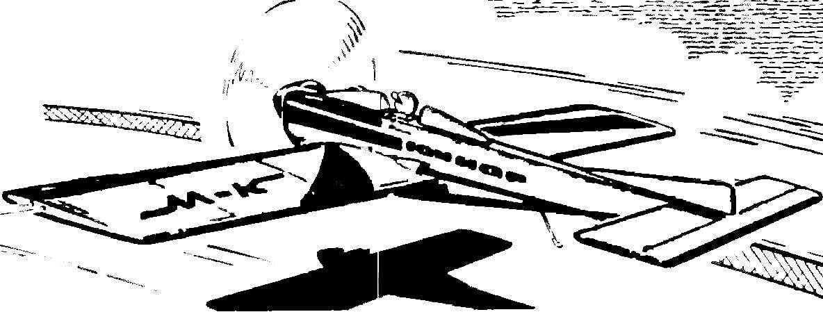
 For a year came into effect new rules on aviation sports, which legalized “school” subclasses of cord aircraft. One of them circuit racing vehicles. Different from “adults” only permit flat fuselages, these models opened the way for many boys in the world-class F2C. For anybody not a secret that, more than in any other class, there still existed an insurmountable barrier for the transition from academic to sports cars. Yes, actually, race training simply did not exist. If you have simplified aerobatic, speed and attack models, racing are required in the beginning to create a championship design. And that was to make the boy who have not yet know which side of the plane take. The classes of racing had to be postponed at times when coming to and experience with different materials, and there will be knowledge in the challenging sport.