BALSA WON’T NEED! OR GLIDER OF THE NEW GENERATION

BALSA DO NOT NEED IT! OR GLIDER OF THE NEW GENERATIONFirst of all look at the model-a benchmark that we have chosen as a “prototype”. This glider was created by the Dutch athletes, having rich experience and traditions in the design of paritala. This model belongs to the most modern developments and has a very high flight performance.

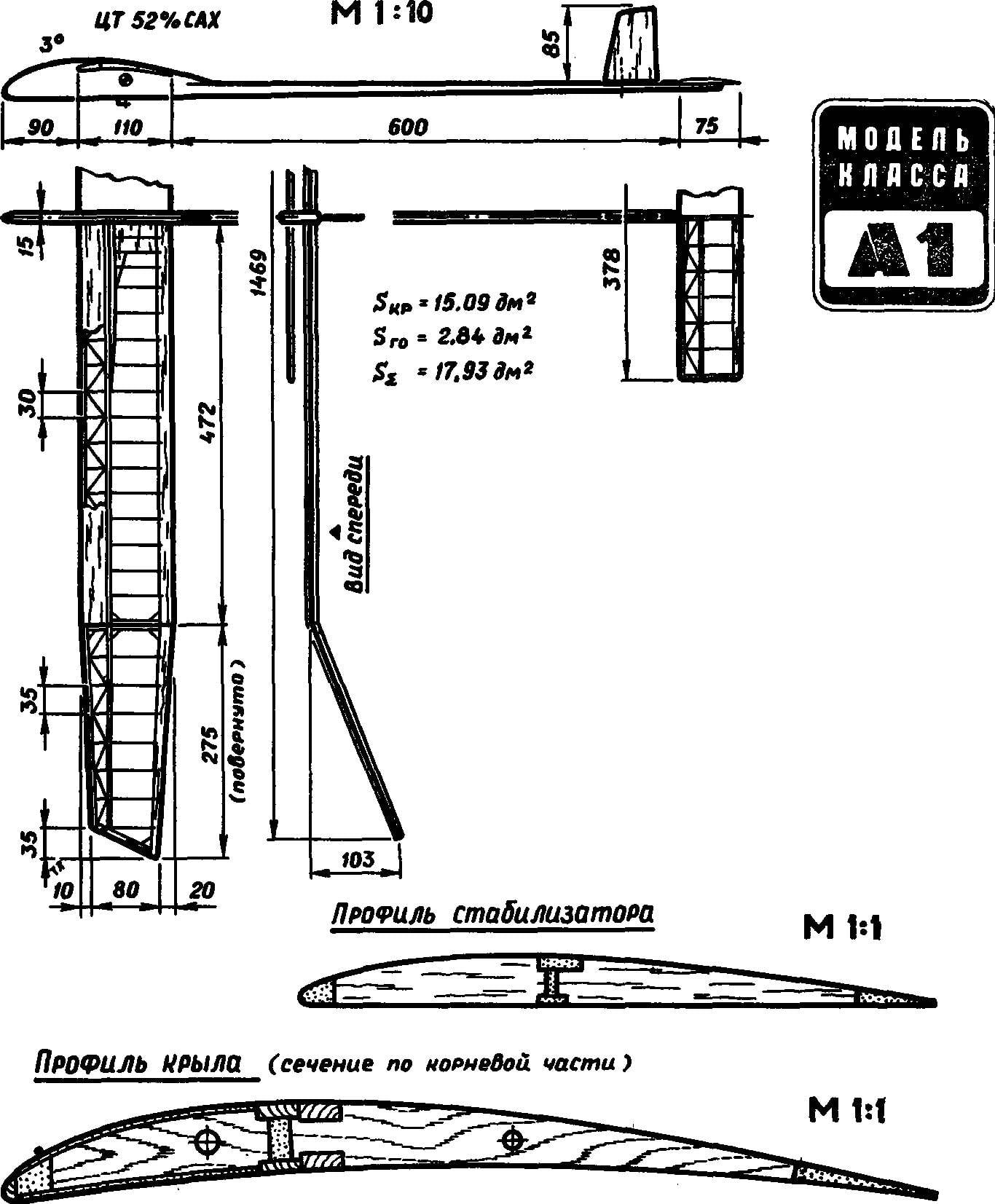
An airfoil having a double — V modified В6356в. The connector on the fuselage; the console must be mounted on two steel pin Ø 2,5 and Ø 2 mm, length 130 mm each. On the power scheme of the wing visible desire of the designer to facilitate the end portions from the mass to the center with a simultaneous increase of the stiffness of the center section.
 
Pine shelves of the spar section 1,5X5 mm (top) and 1,2X5 mm (bottom) in the “ears” to the ending flat out to 1,and 1. 5X3,2×3 mm. across the span of the spar is glued into the wall of balsa with thickness of 3 mm (1 mm “ears”). The root part of the consoles on the shelves are reinforced with additional longitudinal rails 2X5 mm. the Ribs are carved out of solid balsa wood with a thickness of 1.5 mm, and the first four power each console is made of plywood of 1.5 mm. Diagonal polonaruwa of the forehead is balsa with thickness of 0.8 mm. Front edge of the balsa with a cross section of 4X4 mm and reinforcing pine slats 3X3 mm. trailing edge balsa section 3Х17 mm. the Rigid skin of the forehead (obestochennye) balsa thickness 0.8 mm, together with the frame forms a rigid torsion caisson.
 
At the root of the first force between the ribs filled with balsa block, and the second sewn mm balsa. In places of transition between the center section and “ears” have ribs with a thickness of 5 mm. After separate Assembly of these parts of the wing balsa parts podskazhyte at V and are sheathed at the ends with plywood 0.6 mm. And at the interface between the two still embedded, and the balsa plate with a thickness of 0.8 mm. Cording wing — thin long-fibre paper.
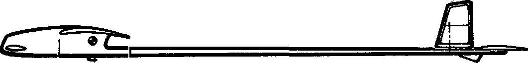
The nose of the fuselage balsa block, lined on both sides with plywood 1.5 mm. Tail boom cone (Ø 15— Ø 10 mm), tubular, laminated of carbon fabric on the mandrel. Fixed tow hook is bent from a steel wire Ø 1,5 mm. stabilizer arched Bed of duralumin sheet; system determinization is triggered from a timer. All-moving vertical tail are made of balsa and light ply.
 
Horizontal tail of a conventional design. The spar is formed by the upper flange of the balsa section 1,5X5 mm and bottom 1X3 mm. To the ends of the cross-section reduced to 1. 5X3 mm and 1X2 mm, respectively. The front edge section of 3X4 mm in the centre reinforced with additional rake from 3X5 mm balsa trailing edge 2X9 mm. the balsa Ribs with a thickness of 1 mm, the spar web and polonaruwa — thickness 0,8 mm.
 
The Central rib of the stabilizer (balsa, 5 mm thick) bears a hook from steel wire Ø 0,5 mm duralumin screw M3,5 for fine adjustment of the angle of attack of the horizontal tail. The suspension unit made of sheet of aluminum of 1 mm thickness ensures reliability of fixation of the stabilizer in flight and clarity of system response of determinization. Cording — thin plastic film.
 
Adjustment begins with the loading of the forward fuselage to obtain the alignment, equal to 52% of the chord of the wing. The angle of the degradation of 3°, the left “eye” is twisted to minus 4 mm, right — to minus 6 mm, centroplane part is smooth. Naturally, the model can be equipped with a tow hook is a modern, mechanized type.
 
Model glider class A1 Dutch athletes.
 
Weight data glider: the weight of the wing (both consoles) — 67 g, the weight of the stabilizer — 5 g, the mass of the fuselage (complete) — 153 g. the Entire model — 225 g.
 
Especially it is necessary to note the high elongation of the wing, which led to an increase in scope to 1,469 mm; large-shoulder horizontal tail and floating keel, broadly in line with trends in “big gliders” class F1A.
 
Now, before I hear from you a resounding “no” to the question, is it possible to create something similar without the balsa, allow me to recommend first, once again see the two publications as “M-K”. This “School microportal for tomorrow” in the number 4 for the year 1989 and “Training on the airwaves” (No. 5 in the same year). If the second article has forced us to reconsider the relation to which were previously unsuitable for the needs of the Antonov an unknown wood density of 0.35…0.4 g/cm3, then the first… About her special subject.
 
When a model glider built exactly according to the drawings of the journal, was finally lacquered, we understand why many have argued that it is not Svobodnaya. Too unusual was in the opinion section of the detail inherent in pereobrazhennya cordovil.
 
But now it became impossible to take seriously no new technology, no… to the old. Heavy-duty models seemed contrary to the testimony of the arrows scales preteenie (by the way, all the weight of parts has been specified in the log with the stock, in fact they are smaller!), while the previous design — a very “pampered”.
 
Having carefully studied the flight capabilities of new technology, came to the conclusion that despite the great “volatility” is only the first step to becoming an amazing scheme. So great seemed the reserves stored in it. The publication shows the drawings is designed for operation A1 in extreme conditions; this model is”tactics”. However, it will not hesitate to take part in the competition, even in the most demanding tours. But with the same model and to undertake the education of the newcomer — she will “forgive” everything.
 
So, the reserves… But before you tell me what model they allowed us to create a bit of theory. Only with it we can determine the applicability of a decision.
 
Let’s start with the Central part of the wing and calculate the strength of main parts. Two steel pins on the Dutch supermodels have a total tensile strength, about equal in tensile strength 200 kg/mm2 for steel (which is high value even for high-quality wire OVS! Moreover, corresponding to full break, not the beginning of the irreversible bending):
 
M1max=0,1*d3*σ=0,1*2,53*200≈300 kg*mm,
 
M2max=0,1*23*200≈160 kg*mm,
 
M1max+M2max=460 kg*mm.
 
We find a similar value for pine shelves of the spar when the limit of compression strength of pine 4.0 kg/mm2:
 
Mmax=a*b*σ*t=17.5 mm2*4*6≈420 kg*mm.
 
(Bravo! Similar values for different parts talking about the literacy of the designer who created the model.)
 
Note that the calculation of the shelves was carried out on the top part because of the directory it is easy to see that for the stretching, bending and compression a number of destructive voltages close to this order: 800, 600 and 400 kg/cm2 for pine, and therefore the bottom shelf, tension, this model can not be assessed.
But the same series of numbers is much more important information. He says that a monolithic spar more profitable! He calculated the bending and not compression. And that’s what happens. Pine timber with a height of 7 mm and a length of the profile chord of about 8 mm to withstand the moment:
 
Mmax=(a*b2*σ)/6=(8*72*6)/6=400 kg*mm!!!
 
The cross-sectional area of such beams is 56 mm2, and both flanges in the classic version — about 30 mm2. But if you now go to the real structures… In typesetting the details still need to take into account the loss to wall, extra long glue joints that in the most stressed parts of glider dvukhpolosnykh spar will withstand the design load only if a very rigid interconnection of the parts condition performed not on all the wings at least due to the use not appropriate to the demands of the adhesives.
 
But that’s not all. After all, if you could add some area to the calculated cross section, then the mass will exclude the entire set forehead when you go to the edge of the spar. The result is amazing! Win on all counts: less weight, greater strength (including V-strengthening the root of the wing of a new model), technology out of competition (is difficult peraleja of thin balsa parts and pine strips — one monopus).
 
How can there still be doubt? The torsional stiffness factor, which is receiving increasing attention while creating paritala with high elongation of the wing? Calculated here to compare schemes will not succeed — there is no technique that is close in reliability of the results. Therefore, it remains one — trial practice. According to our observations and measurements on real wings new sverhpredelna not yield much more power than is set on the Dutch model. And here intervenes another factor, speaking in favor of the edge of the spar. This is the location of the axis stiffness of the console and centering the console on the chord. On new wings, more flexible (up and down) in comparison with composing, deformations are almost unchanged angles of attack. And if so, then the issue of torsional stiffness can generally be removed.
 
Increased bending stiffness, by the way — only on the wing, when the elasticity is set by the introduction of steel pins, and… to a certain extent to the detriment of the new wing. The flexibility allows you to eliminate all the heavy node connector, while sharply raising the reliability of the airframe as a whole.
 
And last wing. At first alarmed the risk weighting of the ends of the plane. But when the scales showed that a fully functional detachable from the center “eye” has a mass of 13 g, the last doubts vanished. Especially when we get in this pattern and sizes can be easily stacked and in 9…10 Just need more practice work on the design so unusual yet technology.
 
I would like to stop at the transit center in the “ears”. How difficult is solved ribs in these areas on the model prototype once more visible — the transition is most prone to failure and unstable to temporary distortions, leashes. A departure from the Central connector and putting it on broken consoles gives you the perfect solution. By the way, concerning remotecodebase.
 
Now people can get to the model. And that’s what she became. We have tried to maintain the basic geometry of the prototype, only slightly changing the wing shape in plan and extending it at the ends, as well as slightly reducing the extension of the stabilizer.

 
Model glider class A1 of the new design.
 
The tail of the model with all-moving keel, and rigid fastening of the stabilizer.
The tail part of the model with all-moving keel, and rigid fastening of the stabilizer.
 
Wing. The leading edge-spar from “white” wood section 8X18 mm to the ends narrows to 4X8 mm, and the “wedge” is made all polarisman. Weight — about 45 In the center wedge section increasing 5X9 mm, which fits over a Central rib (8 mm thickness to the trailing edge tapers to 4 mm). All the ribs of the plates with thickness of 1.5 mm (“ears”) to 2.5 mm (in the center). Ribs at the ends of the connectors like the ending, 3.5 mm thick, and the joints with the front edge reinforced corners-kerchiefs of two-millimeter plywood (sides of 20…25 mm), and at the rear edge — of polutorametrovy (the legs are the same). The joints of all intermediate ribs with the front edge are also embedded in the ribs of the gusset plate. Their thickness is 2 mm, the size in the span of 20…25 mm, and the chord is about 15 mm. All scarves with a semicircular sample on the diagonal; frame Assembly is conducted only on plasticized epoxy resin K-153.
 
Profiling the wing.
Profiling of the wing:
the thin line is the theoretical profile; the dotted line is the real profile with retracting soft skin; the thick contour line of the rib profile modified, built upon deformation of the casing and low-frequency performances of the ribs along the span.
 
Calculation sheet longeron elements in bending.
Calculation sheet longeron elements in bending. Left — dvukhpolosnykh spar (simplified method of calculation of moment of resistance) in the middle of a rectangular beam-longitudinal, right — round pin. Everywhere “X” — axis bending.
 
“Ears” are mounted on the pins of steel tubes Ø 3X0,3 mm, included in the taped holes in the ends of the tube with Kraft paper. In the back — microshift; locking connections or ribbon-tape or tie the thread wound on micrococci. The tight wing — micuenta paper on Amalia, twist similar to the model-prototype.
 
Wing Assembly is integral with “ears”, which are then cut off. Rib of the connector during Assembly are placed with the help of angular templates. All intermediate ribs are using the same template (or one piece, which is then sawn into plates), then the drawing is clipped nose under the edge in this place of the scale and then cropped the shank.
 
The fuselage is completely analogous to the earlier publication in the “M-K”, only the reduced thickness of the bow up to 9 mm and the rake beam became section 9Х11 mm (to end of tail 4,5X5,5 mm). Keel wire, rotatable, with the lower wooden rib. Light weight stabilizer: leading edge section 2,5X7 mm tapers to the ends to 2,5X4 mm, the rear edge is 3X3 mm.
 
And now… hold on! Given the mass of ready-made parts created in accordance with the original design scheme. So: stabilizer (covered with foil) — 5 g, the center section of the wing is 45 g, the “ears” — 2X13=26 g, the fuselage without downloading — 45 total — 121 g plus the keel and the strut of the wing, the hook is just about 130 grams!
Know what you will say: all is well, but the tail ravine… Made in violation of all norms from a single piece of wood, heavy. Yes, carbon-fiber and lighter, and stronger. But the alignment of the conical tube with the same wall thickness compared with cone rail closer to the tail, and this is important, because we are not interested in the absolute weight, but only the moment of inertia! And to reduce best by facilitating the most remote areas (in the calculation of the moment of inertia of the shoulder is inserted into the second degree!). What we did on the new model. By the way, remember the metal parts of the suspension stabilizer on the Dutch model, including duralumin screw M 3.5, which, when the length of the rod 4 mm and weighs not less than 1 g.
 
And to close the subject of strength, we encourage you to read about the comparison of composing and one-piece side members and to take into account that a monolithic beam 9Х11 mm does not break. Or need even stronger?
 
So, relieved of the tail. It is achieved by shortening the second and further narrowing of the beam at the end and… refusing to determinization by using a stabilizer. Creating such an unusual technique, we decided to go on a permutation of the wing (that’s what is more useful to brace — he will keep the wing in the roll), although the most successful would be the permutation of the “ears”. But this thought came to mind when the glider was ready.
 
Flight properties of the model, at least not inferior to balsa devices. But here, the result heavily depends on the debug and on the ability of the athlete to exploit the glider. Therefore, planning in termicznych conditions we do not give — you would not believe… yet do not build this glider.
 
DOLGOV, a candidate master of sports

Recommend to read

  • WITH THE BIKE UNDER THE MOUSEWITH THE BIKE UNDER THE MOUSE
    For those who often have to go up and down with the bike on the stairs, might want a special handle for carrying. It is made of metal tube 18...25 mm and is fixed by welding or clamps to...
  • Lissant – wide profile, advanced technology, high qualityLissant – wide profile, advanced technology, high quality
    PIR-PUR sandwich panels are manufactured by group of companies "Lissant", is the best choice for fast, economical construction of industrial, agricultural, domestic buildings, low-rise...