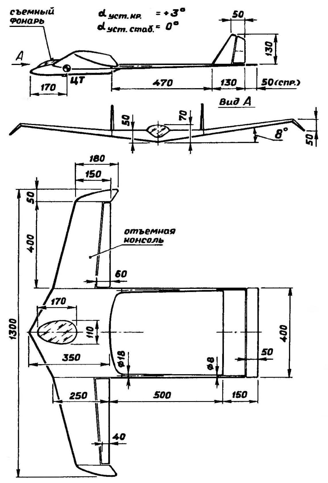
This unusual radio controlled model glider designed in an unconventional scheme: on the one hand, the idea of carrying the fuselage (or “inhabited wing”), the other — hard power structure, constructed as “Rama”. The technology of making a model is the light-tight foam of the rigid elements of the bearing lining. The most loaded zones are enhanced with pine slats. This applies primarily to longeron nodes and edges, as well as composing, not having the foam “cores”, rudders and ailerons with a soft covering.
THE RELATIVE COORDINATES OF THE AIRFOIL

RELATIVE COORDINATES OF THE PROFILE OF THE STABILIZER

THE BASIC DATA MODEL
The area of Creel, DM2 …………………………………………………………………………….30
The surface of the stabilizer, DM2…………………………………………….6
Efficiency of the stabilizer…………………….0,6
Lengthening of a wing……………………………………………………………..5,2
Extension of the stabilizer………………………………………………..2,6
The mean aerodynamic chord, mm………………………………240
Alignment SAH…………………………………………………………………25
Takeoff weight, g…………………………………………………………….750
The relative load on the wing, g/DM2…………………………..25
WEIGHT CHARACTERISTICS MODEL
The center section ……………………………………………………………………160
Wing…………………………………………………………………2х70=140
The tail boom………………………………………………………………2×15=30
Horizontal tailplane………………………………..30
The vertical tail……………………………………2×5=10
Lantern……………………………………………………………………………20
Battery pack-batteries……………………………………………100
Receiver with steering servo……………………………………150
Ballast …………………………………………………………………………160
Total:……………………………………………………………………………..800
Despite the use of the filler melkosortnogo polystyrene foam, density of detail varies. So, the density of the center section, covered with glass fiber epoxy resin, is 12 g/дм5, wings with a covering of paper — 8 g/dm2, and the fixed elements of the empennage, similar in design to the consoles of the wing,— 5 g/dm2. The tail boom is made in form of tubes made of fiberglass. The lantern, closing the compartment of the instrument, made of hot-Plexiglas with a thickness of 1 mm.

Fig. 1. RC training model of the airframe of new type.

Fig. 2. Layout scheme of the model.

Fig. 3. The wing profiles (A) and stabilizer (B) constructed by the given coordinates.
The proposed airframe is simple to manufacture and technologically advanced, and its construction does not require complex tooling. Ballast is used to balance almost pronounced a model could be abolished, if you set the on Board batteries uvelichenii capacity.
V. the SCRIBES, Saint-Petersburg


