After creating working drawings and interconnection of the nodes was built three geometrically identical models, differing from each other only power circuit and motor units (and consequently the specific load on the bearing surface). All three tests showed that with a neat faultless performance microplane its aerodynamic configuration to meet the requirements within a wide range. Model taking off without any problems not with the chassis, and with the hands; flight even in windy weather resistant; responsive control in all axes, and at smaller angles of deflection of the rudders degree of stability allows you to comfortably entrust the piloting, even for beginners. When the rudders completely rejected any modification of a micro-airplane with sufficient power motor easily “twists” the basic aerobatics.
Very broad opportunities both in terms of initial training and the development of skills of piloting this model with two-channel control (Elevator and ailerons). Of course, anyone can try and a classic Elevator and rudder dual-channel option. However, it appears that this “beginners” not only will be limited by the degree of proteraiotita, but also will give the pilot next to useless skills inherent in this complicated management.
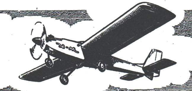
Shown in the figures, the modification of the aircraft – the main. It is designed for three-channel instrument (with a mass of side portion of about 250 g) and a good reliable engine KMD. Requirements for high capacity are not required, since takeoff weight of the apparatus is in the range of 1350 grams without landing gear, and thrust enough even for unextended vertical figures (this, of course, when properly adjusted air screw). Lightweight same model in assassina performance have a takeoff weight of about 1000 g and confidently fly even with motors of the “Rhythm” or MK-12V. But it’s better to use the same KMD, working in a softer mode.
Fuselage:
1 – motor mount (plywood 6…8); 2 – wedge insert (Linden 4); 3 – front top stringer pine (4); 4 – falsetto side of the fuel tank (plywood 1); 5 – cover (dugout detail of lime); 6 – plate of wood (plywood 2); 7 – Logement surface (thin foam); 8 – contour of the wing; 9 – Board (plywood 1,2); 10 – jumper sheathing (plywood 1); 11 – pin (Buk d6); 12 – top stringer (pine 4×9 on all length); 13 – frames (plywood 2); 14 – brace (pine 2,5×4); 15 – spacer (pine 2,5×4); 16 – dorsal fin (Linden 2); 17, 23, 30 – items covering the tail node (plywood 1); 18 – triangular rail amplification of the junction of the keel with a stabilizer; 19 – the edge (pine 4×6); 20 – bracings are pine (2. 5×4); 21 – ending (Linden 4); 22 is a window for the passage of rods; 24 – bottom stringer (pine 4×4); 25 – the back of the lower sheathing (plywood 1,2); 26 – base (plywood 4); 27 – strengthening of Board (plywood 4); 28 – front lower trim panel (plywood 1,2); 29 arc edge (plywood 2); 31 – the front frame (plywood 5… 6); 32 – double-stringer (pine 4×9).
Front removable landing gear:
1 – hooks (curved long M3 screws from high-quality steel); 2 – the front frame of the fuselage; 3 – strut of the front wheel (wire OVS d3,5)
Rear removable rack chassis:
1 – strengthening the side of the fuselage (plywood 4); 2 – front bottom plating; 3 – rack (wire OVS d3); 4 – lining (steel 1); 5 – screws; 6 – frame (plywood 2); 7 – rear part of the bottom plating; 8 – base (plywood of 4)
If it is possible to reduce the cross-section strips on a portion of their length with vibrolance, the main stringers of the fuselage to carry the main section mm 5×5 and 5×9 mm. Plywood shell elements punch in the slats flush.
Design of parts and components of this model are fairly well known to the Modeler at any level. Therefore, its manufacture the attention of the reader can not stop. I can only say that in any case the main link in the Assembly of power frames and assemblies is solely plasticized epoxy resin K-153. Cover all surfaces of the Mylar film is the average thickness on the glue “Moment” (cutback solvent for nitropaints) or N-88.
Wing (basic version):
1 – tight foam head (thin paper in PVA); 2 – rib (plywood 2); 3 – foam forehead (profile received by the processing unit according to the templates using thermotron; the mass of the forehead of packing foam about 30 g without the plating of the SS-4-40 – 45 g); 4 – shelf side member (pine 4×5); 5 – the leading edge (Linden 2,5×8); 6 – plate splice of the spar (plywood 1.2 mm over the entire height of the profile); 7 – framing of the compartment steering cars (lime); 8 – polonaruwa; 9 – the growing edge (pine 5×9); 10 – power Polonnaruwa (to put in the pin mounting of the wing on the fuselage); 11 – the covering of the wing (plywood 1); 12 – front side member cover plate (plywood 1,2); 13-additional rib (plywood 2); 14 – boss (set with pin attachment of the wing to the fuselage); 15 – torsion actuator Aileron; 16 – additional shanks (plywood 1,2); 17 – wall edge pine (3×5); 18 – the trailing edge (pine 5×9); 19 – Aileron (dense balsa or light lime 7×30); 20 – the fairing edges (light lime); 21 – ending (plywood 3); 22 – oblique Polonnaruwa (plywood 2); 23 – insert the end of the spar (lime 5).
The wing – Mylar film thickness of 25 microns over the entire area
Wing light:
1 – additional rear flange (pine 3×7); 2 – ending (plywood 2); 3 – bracing pine (3×3); 4 – pad front edge (pine or basswood 2,5×10); 5 – the leading edge pine (5×5); 6 – Polonnaruwa (plywood 1,5); 7 – rib (plywood 1,5); 8 – shelf side member (pine 4×5); 9 – strengthening the front edge of the pine (ZKH 15); 10 – additional Central spar wall (plywood 1.5 mm over the entire height); 11 – compartment steering cars; 12 – power rib (plywood 3); 13 – strengthening edge pine (5×12); 14 – shank-plate (plywood 1,5); 15 – tough sheathing (plywood or 1 mm on cardboard, some on the forehead of center); 16 – shank (plywood 1,5); 17 – torsion actuator Aileron (aluminum knitting needle…d3 3,5); 18 – the edge (pine 2,5×5, two strips); 19 insert (Linden 5); 20 – wall edges (plywood 1); 21 – shank ribs
Profiles and ribs of the wing light:
a – basic version; b – variant with a hard skin of the forehead, insulation thickness of 0.5 mm (weight of plating of about 70 g) and extra nose ribs of the foam plates with a thickness of 2 mm; In the version with the hard skin of the forehead with a double layer of glued paper (weight of skin about 40 g), foam ribs, banded with strips of cardboard and getcoursename ailerons
Stabilizer:
1 – ending (Linden 4); 2 – edge pine (4×5); 3 – braces (2×4 pine); 4 – rib pine (3×4); 5 – a lining of the center (cardboard); 6 – strengthening edge pine (4×4); 7 – trailing edge pine (4×4); 8 – jumper (pine 4×6); 9 – wheel height (light basswood or balsa);
a – set of the stabilizer of the plates pine 4 mm thick; b – variant of the stabilizer is filled with a foam type packing, with a covering of paper (center) and thin paper (across the surface); In – variant with dramatically light weight set of slats 2×4 mm with power shell made of cardboard (a weight of 40 g on the casing of the stabilizer with rudder)
Advantages of flight characteristics “school” can say modelers another modification of the microplane. But first you should deal with the masses of its individual parts. So, directly to the frame (with a takeoff weight of 1350 g) only 760 grams, and still it is necessary to subtract the mass loss for close-fitting, varnishing and painting. Rough calculations show that the net mass of the frame of the average strength of about 680 – 700 g. Now try to repeat the weight distribution, putting a specific load on the supporting surface 70 g/dm2. Such has many of the Western models built from kits manufactured there-packages.
I think that the calculations will give unexpected results. The fact that during the takeoff weight 2540 g, and a constant weight of the side of the instrument is given a heavier power plant, on the frame it will be possible to take… twice more! This means that before you open the prospects of creating an extremely durable model. After all, double the stock weight definitely increases the thickness of all sheet metal parts in half and section the core elements 1.4. Draw your own conclusions… just have to Express bewilderment, where the creators sets for mail-order machines, the main material is balsa, laid the excess weight.
In conclusion, the angles of deviations of the rudders on the proposed “island”: the Elevator ±20°, rudder ±25° and the ailerons ±15°. As already mentioned, during initial pilot training is helpful to reduce rates due to the change of the shoulders of the transfer levers about half.
V. KIBETS
Recommend to read THE INVISIBLE WATCHMAN Generators of low frequency oscillations, as is known, can be used as a caretaker: intermittent loud noises warn of the approach of a stranger. On the same principle and made our... GLAZE VERANDA FILM Your house is almost built. Left to be glazed veranda. But do not rush to buy frames and order glasses — there is another solution, cheaper and easy. Let's see how this looks porch... Scroll back to top
 Despite various difficulties faced by modelers, RC aircraft are still interested in this most complex kind of modeling. Everyone who chose a specific type of equipment, immediately the question arises a considerable difficulty: how to lay model? The solution of this problem on the proposed development. The main principles which form the basis in the design of this RC model, steel of sufficient simplicity, accessibility and, most importantly, the high performance characteristics at different flight speeds and specific loads.