BIRD

LIKE A BIRDStories about the competition Experiment, systematically held in our country attract attention of not only athletes modelers, but readers are far from this sport. So unusual look time, rezinomotornaya and gliders-“wings”, even a cursory view of the magazine of their photographs compel us to pay attention.
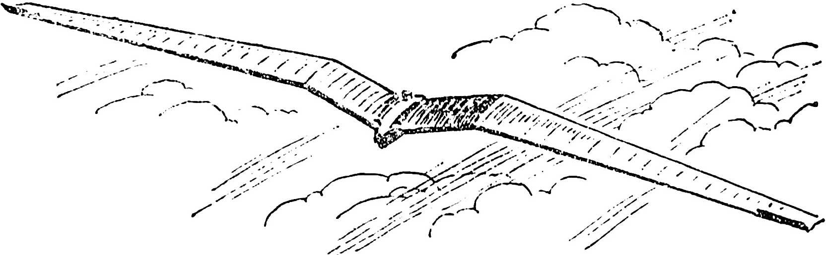
However, models of gliders, successfully used in the competition “family crew” — L. Klimov and his son Yuri — surprise even experienced the “experimenters”. The fact that the soaring leader-the”wing” has already swept the unusual shape, and in plan resembles the letter M. Yes, and the front model is unusual — a transverse V-wing set according to the scheme of “the Seagull.” As a result, the soaring leader Klimov are so similar in flight on this bird, what made once deceived even the dog. She ran behind the glider in the hope about to catch sitting down on the field “game”.
 
But the outward signs of this new model. Is it ever justified from the point of view of aerodynamics, bring any improvement in flight characteristics of soaring leader? In saying this brilliant performance of Klimov at the event.
 
The wing, as already mentioned, the plan is similar in form the letter M. the Central part with a constant chord and back sweep 5°, console areas with a significant narrowing of the direct sweep of 30° to the front edge. The transverse V is formed by setting the center of the wing at 15° from the front, then after the bend shape angle reduced to 5°.
In addition, console areas and have a substantial negative twist of 12° to ensure that longitudinal balance of the machine, for the same purpose at the ends of the wing are mounted special plates. Wing profile follows the profile drawn by the famous Soviet Modeler A. Leppo.
 
Fig. 1. Model glider pilot class.
Fig. 1. Model glider pilot class:
1 — shield, 2 — cantilever part of the wing 3 — the Central part of the wing, 4 — fuselage.
 
The constructive scheme of the wing is single-spar, all operations at its Assembly held on the stocks, which gives the possibility to simplify the serial production of paritala.
 
In the Central part of the wing spar is formed by two pine rails-shelves-section 11X2,5 mm in the root of the cantilever sections of the cross section of these elements is the same, to the end it is reduced to 6X1,5 mm. Front edge of the wing pine rack 5X3 mm constant cross-section. Posterior — triangular profile — pine rail 3X20 mm, from fracture of the contour of the wing tapering towards its end to 2X12 mm.
 
Ribs and Polonnaruwa carved from Linden veneer 1.2 mm thick, for each section of the wing they are processed in the batch on the metal profile template. The end ribs in places of contact of the wing is made of five millimeter plywood, they are mounted on the extreme fake ribs. The space between the two ribs at the root of each wing is sewn around the contour of the profile balsa veneer thickness of 1.5 mm. Ending — balsa, with a thickness of 10 mm, in the form of repeating the profile of the supporting planes. The break of the contour of the wing is reinforced with lime insert 3X20X200 mm. After Assembly of the main frame polacrilin between the ribs and polynorborene is glued in the spar web of fake millimeter veneer.
 
In the first six ribs of the root section of each of polycrylic orifices in the partition are stuck with the balsa sticks pre-drilled in them longitudinal channels Ø 3 mm under the connector pins. The last (two) — heat-treated high quality steel wire Ø 3 mm, length 250 mm. Before installing on the model of their bend at an angle of 30 ° exactly in the middle.
 
The tight wing is made with long-fibre paper, covered after covering the four layers of the liquid Amalita. Twist the console sections of the wing under the influence of steam; the “heat” from 15 to 20 min. On the ends of the bearing planes are mounted flaps. These elements performing the functions of the organs longitudinal balance, two-millimeter cut from the balsa plate, both sides covered with paper and proamerican. When adjusting the flight, the flaps deflect by putting a thin plates under stops, their position is fixed with adhesive tape-adhesive tape.
The fuselage is actually the element that unites all parts and components of models in one unit. It contains the mechanism of forced landing, the clockwork, the ballast weight, pins hitch polycrylic and start the hook. Harvesting of the fuselage is assembled from two side panels (mm plywood), between which a sealed insert of lime with a thickness of 6 mm. After the installation of the pins in the fuselage they put a fake plate-rib and bonded to the sidewalls. In the upper part of the fuselage hollows out a recess under the clock, next to him is the cradle of the thread, holding a balance weight in the position. The load itself is placed in the rail steel tube Ø 12X0,5 mm and is preloaded by a spring to the lever. Vvorachivaya and twisting the adjustment screw, easy in accordance with the position of the center of gravity of the model glider. In the cocked position of the mechanism on the screw wound nylon thread length of about 500 mm, the end of it is attached to the fuselage. After triggering the mechanism of forced landing, the lever releases the spring, which pushes the balance weight from the fuselage. The center of gravity of the machine dramatically shifted, added to this is a leap from the thread holding the discarded goods as a result, the glider moves to parauterine.
 
Fig. 2. The fuselage of the model.
Fig. 2. The fuselage of the model:
1 — clockwork, 2 — lever, 3 — loop (line Ø 0.3 mm), 4 — the screw of adjustment of the load position M3, 5 — rear arm (wire 0,8 mm Ø), 6 the thread of retention, 7 — tow hook, 8 — centering weight, 9 — guide pipe, 10 — spring release of cargo, 11 — pin hinge of the wing.
 
Fig. 3. Templates for building the profile of the ribs (shown in the root and end rib consoles).
 
Tow hook is sawn from a sheet of aluminum with a thickness of 6 mm. it is Attached by two M3 screws with nuts at the bottom of the fuselage. The possibility of moving the hook along the fuselage when adjusting the mode of towing a glider.
 
After finishing work on the individual elements is made by a test Assembly model. When installed on pins polacrilex gaps between the root ribs and the fuselage should not be, the density of connections is achieved by the screed consoles of the rubber thread wound on glued to the root ribs celluloid hooks.
 
Then you should monitor polycrylic symmetry and the absence of unspecified twists, leash. If testing will prove that one console is heavier than the other lightweight dorozhayut. Flaps should be rejected at the same angle, the center of gravity due to the selection of the position of the balancing weight is brought to 50 mm in front of the rear edge of the center section of the wing, also verified the mechanism of the forced landing and clockwork. The mass of the model, prepared for the opening of not less than 410
The first flights it is best to start with the light breeze. Holding the glider at the fuselage, make a few runs against the wind. The model should not show a tendency to roll. On planning her release with a weak push, immediately controlled the straightness of flight. If the glider is flying “sideways”, is eliminated, changing the installation angle of the flaps.
 
Then start working on balancing planning mode due to selection of the alignment and installation angle of the flaps. Finding the alignment that provides a gentle path planning, installing tow hook 10-15 mm in front of the center of gravity of the model. When it runs on the guard rails glider is available in a flight definitely, and giving it some horizontal velocity. This condition should be observed even with a mild wind, the push can be excluded only in the fresh headwind.
 
A well-established model flying bends of large radius. The skillful determination of atmospheric conditions and the correct run duration of flying “wing” — 2 to 3 min.
 
The basic data model glider
 
The area of the carrier, DM2: 33,5
 
Takeoff weight, g: 415
 
The angle of twist of consoles, grad.: 12
 
L. KLIMOV, engineer

Recommend to read

  • THE HOSE ON THE PIPE? IT’S EASY!THE HOSE ON THE PIPE? IT’S EASY!
    It is sometimes necessary to put a rubber hose on the pipe, the outer diameter of which is somewhat larger than the inside of the hose. Will be able to help out a little trick: just cut...
  • BARBECUE-COTBARBECUE-COT
    Usually barbecues and barbecue for barbecue or roasted meat, a heavy box-shaped device of heat-resistant metal, welded, riveted or cast housings, mounted on legs. The illustration shows...