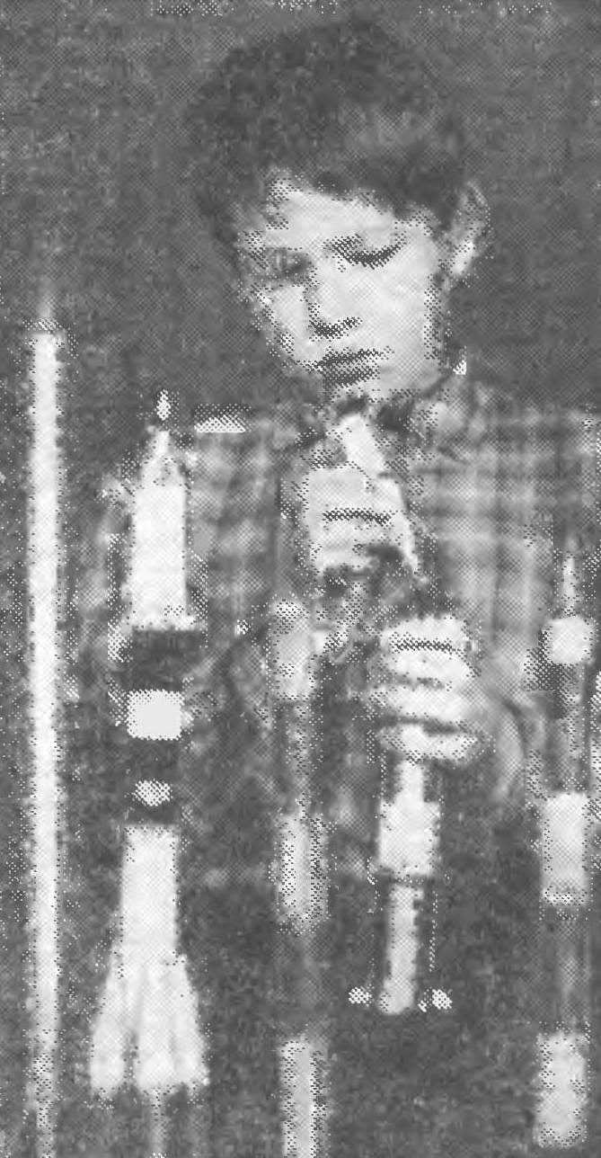
 -Models of missiles doesn’t need to be. Do them and run interesting. Special, with nothing comparable to the excitement you experience the designers of such models, participating with them in competitions. In our country there are competitions copies missiles on high, and the realism of the flight. It must be borne in mind when designing future models.
The editors have received many letters asking to tell about the basic techniques of manufacture of this class of missiles. In No. 2, 6 and 8 of the journal for 1976 was published some materials about the basics of rakotondravony. In this article we describe the construction of simple models available to the members of the second year.
Where to start! This question arises from a Modeler who wanted to build a model copy. The answer is simple — with a drawing of the prototype, the collection of the necessary information about the missile or the launch vehicle of the space object: technical data (length, diameter, etc.) and photos appearance. Unfortunately, such information is printed is not enough. That’s why for beginners “copyists” it is better to repeat the copy on the finished drawings.
At this, the first stage of the design model, it is necessary to determine in which category you will compete. So, for starts, altitude (class S-5) it is advisable to call missiles with high elongation, than to compete on the realism of the flight (class 8-7). From aerodynamics it is known that, the greater the lengthening of the rocket, the more stable its flight. Beginning “missile” it is better to take up the construction of simple models with symmetry body, aerodynamic stabilizers. It is primarily easy to fly copies of the first Soviet missiles 09, R-03, R-05, R-06,-5 -, and others.
Before you draw a working drawing of the model, it is necessary to determine the scale. If the picture of the prototype dimensions of a missile of this completely, separate them at the scale of the reduction and get the dimensional data model. But often, the original drawing shows all dimensions. In this case we have maximum accuracy (preferably to tenths of a millimeter) using a ruler, to fathom the geometrical parameters (length, width, etc.) on the figure to multiply the values on the scale increase.
Here, for example, how is the calculation of these missiles “meteor-1”. The diameter of the housing at the bottom — 120 mm Outer diameter flying engine MRD-10, which will be provided to the model — 20 mm Select a number greater than 20, in which 120 is divisible. It will be 24. Divide 120 by 24, the number 5 will be the scale of the reduction model. Left to share all the dimensions of the missiles at 5, and geometric data copies are done. It should be noted that the scale model does not have to be an integer. Sometimes he can be shot.

Fig. 1. The motor mount using the clip: 1 — the stabilizer, 2 — clip, 3 — engine, 4-chassis.
Fig. 2. Gluing the butt joints of the sections: 1 — section of the housing 2 — petals.
Fig. 3. Gluing the case of complex shape: 1 — section of the housing 2 is a power tube, 3 — frames.
Fig. 4. Motor mount: 1 — power frames, 2 — stabilizer, 3 — engine. 4 — the case.
Fig. 5. “The engine room” of multi-engine model: 1 — body, 2 — blanks, 3-frames.
Fig. 6. Division steps: 1 — the case of the first stage, 2 boss, 3 — reducer sleeve, 4 — the case of the second stage.
When choosing a scale copy of the model, one should also know what engines it will run. their exact dimensions. The main defining size — the diameter of the body should be 2-3 mm larger than the motor, which is fixed via a sealing with a paper clip (Fig. 1). The latter will create an air layer between the engine and the housing and prevent it from burning out.
Finally, a working drawing is made. It’s time to take up the construction. Usually start with the hull. There are many ways of its manufacture. The easiest, though not very practical — to the gluing of drawing papers. It is necessary to prepare a mandrel of a diameter less than the diameter of the body. 1 mm. If the housing of complex shape, you will need a mandrel for each section. Glued blanks butt on the bars, holding them in the Chuck of the lathe, and on low speed, cut sharply honed scalpel. Glue a section of comfortable petals out of paper (Fig. 2). There is another, more practical option. Of paper, folded in two layers, glued together Central strength up. Put on plywood formers, and then the body sections and their joints must coincide with the frames (Fig. 3). The case made on such technology, has good strength, but heavy. It is better to apply the fiberglass.
The next stage — making “power compartment” — engine mounts. The easiest way (using a holder) we have already spoken. But there are other options. Assume that the diameter of the body in the rear 30-35 mm. Here it is better to use power frames (Fig. 4) out of plywood with a thickness of 2-3 mm. If the model installs a number of engines without frames to do the impossible. They cut a hole under the engines and glued into the housing (Fig. 5). In order to avoid distortions of frames during gluing reinstall engines or pre-prepared blanks.
In multi-models to separate stages of the case you can use the bushing and the boss (Fig. 6).
The most common material for stabilizers — lime veneer. In models-copies, stabilizers thickness not exceeding 2 mm, it is possible to use plywood. Here’s how it’s done. Cut two metal template. Having fixed between them in a vise stabilizers, process last file (Fig. 7).
Note mount the finished stabilizers to the body. Glue-on butt not always provide sufficient strength. Reliable bonding using stud bolts (Fig. 9). They are made from steel wire Ø1—1.5 mm, and the stabilizers are fixed on the housing with epoxy. Many of the “rocketeers” increase the area of bonding, applying spikes (Fig. 9b). We also produce a small area of the stabilizers of paper (Fig. 9b).
Processing fairings is a little different from the usual. Without a lathe almost impossible to imagine. But for some copies of the fairings could be carefully cut with a knife from lime, aspen or birch. The cargo hold for ballast is a hole in the head fairing. Ballast secure, better — skate.
Rubber shock absorber can be attached to the parent fairing methods are shown in figures 8A and b. Ring of steel wire Ø1— 1.5 mm glued to the part of the cone that is inserted into the housing.
To the guide rings of the model copy to meet such requirements. They must guarantee reliable acceleration on the guide pin and to be secured to ensure the safety of takeoff. They need to do unobtrusive, and the fastening is reliable. The easiest way to bend them out of metal strips with a width of 1.5—2 mm and replaced by epoxy resin (Fig. 10). Another way. Glue from the fiberglass tube Ø 7-8 mm, cut into rings and glued to the hull with epoxy glue. They have to be placed so that they dimmed the other elements of the design model.
A few words about the parachute. It is necessary for trouble-free descent: in fact, according to the rules of the competition, the model must be able to make a repeat Pope. The area of a dome is selected depending on the weight of the model. Normal (based on practice) can be considered as the load on the parachute is equal to 25-30 g/dm2. Made the dome more often made of a light fabric or a long fiber paper.

Fig. 7. Processing stabilizers in the grip: 1 — patterns, 2 stabilizers, 3 — vise
Fig. 8. Options for shock absorber attachment: a — groove; b — for bracket.
Fig. 9. Mounting options stabilizers: a — heel: 1 — housing 2 — stud 3 — stabilizer; b — on thorns: 1 — body, 2 cutouts for the spikes, 3 spikes stabilizer; in paper valve: 1— body, 2 — paper stabilizer.
Fig. 10. Mount the guide ring to the housing.
The final stage is painting and finishing. They should be given special attention, because from the appearance of the poster depends on the rating of miniature missiles. The model weighed (PI she meets the requirements of this category?) and re-measure. If there are deviations of geometrical parameters that need to be addressed. Then cover copy two or three times a nitrocellulose lacquer or glue AK-20. After drying each layer treat the surface with sandpaper. Discovered irregularities putty. Then clean up these places with sandpaper (so that it is not clogged with putty, apply kerosene, water, and even better gasoline — it does not moisturize the paper and the wooden parts). In conclusion, once again covering the rocket with liquid nitro lacquer, preferably from a spray.
If the coloring of the model, there are bright colors, it should first be painted with silver. This paint covers well any other color. We offer one of the ways to prepare a paint. Aluminum dust washed down with liquid nitro lacquer (Amalita) and well mixed, then give the mixture to settle. After 5-6 hours, when heavy particles will fall into the siege, drained 3/4 the volume of the paint and use this memory to work.
Painting the entire model, proceed to tagging and labeling. Small labels usually write with a pen using liquid nitro. The layout of the sheets (video) is performed by the spring. This work is carried out with special care. Using gouache model had varnish.
V. ROZHKOV


