 We offer an interesting model of Leningrad designers B. Abramova and V. Alexeeva — a rocket complex with — cancer heated — designed for the Modeler, already built such devices and are familiar with the theory and practice of their launch.
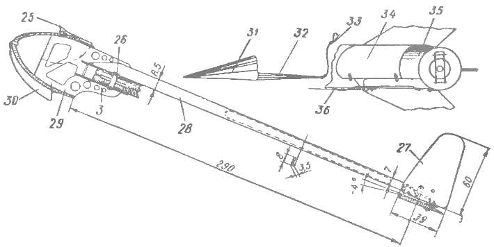
The body of the rocket container glued one layer of quality drawing paper on the mandrel. Top body reinforced filament ring. Bushing, load a number of functions, carved from dense foam. In its internal cavity contained a tube of drawing paper, its inner diameter equal to the diameter of the sleeve of the standard charge. On top of the glass is glued a plywood ring, its main purpose to strengthen the plate, which held the cartridge case by the combustion of the expelling charge. The plates are joined to the retaining linchpin. The stabilizers of rockets are made of plywood with a thickness of 1 mm with a window of relief pasted over with two parties tissue paper. Cut part of the wall of the rocket between the two stabilizers turned into the flap of the parachute compartment. Compartment holds vomitory parachute. It is made of mcalenney paper. The diameter of the dome — 380 mm. By order of the air parachute attached, model rubber band carbine, length 180 mm.
Once stowed in the parachute compartment and door is locked by cotter, parachute stretched rubber band and its carabiner-fastened to the bracket. For power transmission expelling charge rocket plane has stock. It consists of a rod and piston. Stock rounded ring passes through the guides and rests in the bracket of the left wing (it is in attachment 3 — bottom).
For reuse of the piston and rod, it is also equipped with an elastic band with a clasp, its length of 120 mm To the point of entering the folded rocket plane in the body of the rocket elastic band is fastened on the bracket so that when the actuation rod together with the rocket, as one descends on a parachute.
The fuselage of raketoplana consists of beams and fairing. In the fairing affixed to the attachment point of the wing. The plywood frame is the basis that connects the parts of the unit. Celluloid brackets glued in corresponding grooves of the fairing. They perceive significant effort dual bands, which reveal the wing with the departure of the rocket from the launch container. Landing skid made of wire Ø 0,5 mm. Locking the flight-swept wings is nylon thread, firmly embedded in the beam and the wings of celluloid plates and wedge-shaped wooden pins with glue.
The wing is made from balsa plates size mm. 460X45X5 Giving the wing the exact shape in plan, its upper profile of the shackle. After that, over heated metal plate on the shaded place is bend corresponding to the mounting angle is +3°, and then processed by the lower concave arc of the wing profile. To reduce friction and greater strength of the Central part of the wing are reinforced celluloid washers. Axis of the wing is brass tube. The wing is attached to the ends of the center section, metal hinges, steel their diameter of 0.4 mm are as torsion, holding the console at an angle of 30°. The loops are wrapped with a thin thread of glue is inserted in the slot of center console. To facilitate the lower part of the stabilizer selected a chisel and are covered with condenser paper. The keel is flat, hinged to the stabilizer gives him the opportunity to develop along the stabilizer and the stabilizer on the wire axis is rotated at 90° and fits the contour of the folded wing. In flight position all the tail is set with a total rubber band threaded through a hole celluloid stand. Locking the vertical position of the keel is made of millimeter celluloid. Is the lock stabilizer.
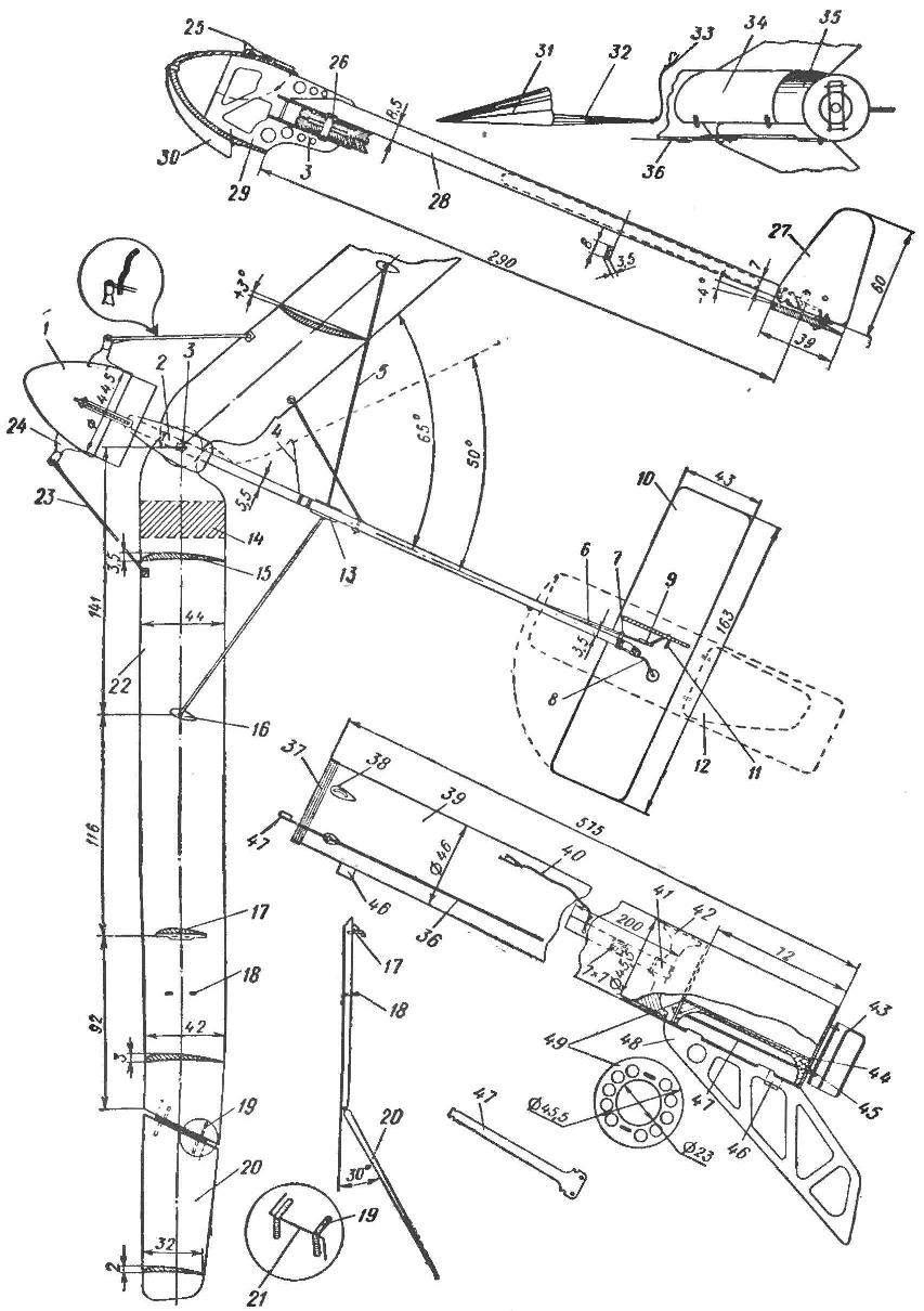
1 — nose cone; 2 — celluloid washer; 3 — plate wing mounting (plywood — 1.5 mm); 4 — wire-stop (OVS Ø 0,4 mm); 5 — retainer wing (nylon thread); 6— elastic return of the stabilizer; 7 — lock stabilizer (celluloid); 8 —axis of rotation of the stabilizer (OBC Ø 1 mm); 9 — guide rail strut; 10 —stabilizer (balsa); 11—lock keel (celluloid); 12 — the outline of the relief of the stabilizer; 13 — celluloid panel; 14 — bend angle; 15 — the profile of the wing; 16 — celluloid panel; 17 — emphasis of stem (celluloid); 18 — guide rod (celluloid); 19 — hinge (tin); 20 console wing (balsa); 21 — the axis of rotation of the console (OMC, Ø 0.4 mm); 22 — wing (balsa); 23 — the elastic return of the wing is in gliding position; 24 — bracket (celluloid— 1.5 mm); 25 — the lever of inclusion of a parachute (D16, 1.5 mm); 26 — axis of the wing hinge (brass Ø 4 mm); 27 —keel (balsa); 28 — the fuselage-beam (balsa); 29 — a connecting frame (plywood — 1 mm); 30 — landing skid (OBC Ø 0.5 mm); 31 — parachute (micuenta paper); 32 — the parachute lines; 33 — carbine chute; 34 — fold the parachute compartment; 35 — compartment chute; 36 — lock check (OVS Ø 2 mm); 37 — thread ring; 38 — bracket (celluloid — 1.5 mm); 39 — the body of the rocket (drawing paper); 40 — rubber band with carabiner; 41—rod (balsa); 42, a piston (foam); 43 —retaining check (OVS Ø 1 mm); 44 — tube sleeve (drawing paper); 45— seal (foam); 46 — the guide rings (drawing paper); 47 — pull locking checks; 48 — stabilizer (plywood); 49 — ring (plywood — 1 mm)
In the design of complex one of the master nodes is part of the parachute compartment. It is placed in the bottom of the rocket to prevent breakage of the rocket plane in two possible circumstances. The first case is when insufficient power lifting charge could only move the rocket by a few millimeters. The second case is when the explosion of the main engine occurred in the mode of climb. As in the first and in the second case, the parachute will instantly reveal and ensure the safe landing of the complex.
The interaction of the parts of parachute mechanism is the following: is the rocket to start moving under the action of the lifting charge as Duplessy lever being in engagement with the retaining loop checks, will release the sash, and a parachute under the action of the stretched elastic bands are instantly revealed. The lever, losing the prop, spins around, leaving the pin in the body of the rocket in the guide. The second case is very rare. If you explode the engine, the bushing and the lower part of the missiles is destroyed, and does not hold the parachute down a rocket with a rocket plane.
Steady gliding flight of the rocket plane under normal weather conditions lasts 2-3 minutes, but the ascending air currents can carry it, and in this case, the loss model almost inevitable. A similar fact occurred, he was forced to enter into the design of a simple but reliable mechanization.
In rubber ring, right side of center thread and with its help it is attached to the bracket. Thread is inserted between the wick (this is soaked in a concentrated solution of potassium permanganate, cotton lace). When to start seconds designed for burning duration of 2.5—3 min. the wick ignited. In gliding flight, a smoldering wick burn through the fastening thread, and a rubber ring is released, and a single elastic band takes the right wing to wire the stop, thus increasing the sweep to 50°. Broken wing rocket plane enters into a spin or a spiral dive. Start of the complex with a conventional rod where it is held by the guide rings.
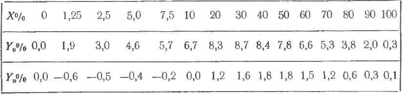
THE PROFILE OF THE WING ROCKET PLANE
Skaka all parts being nitrocream.
The weight of the rocket container with full detailing 46 g. the weight of the gliding apparatus 40 take-off weight of the complex. 115 in
Recommend to read
 GREENHOUSE BIOFUEL
The greenhouse is hardly surprising. As in the days of V. dal, compiler of dictionary of the living great Russian, it's all familiar "hothouse without the furnace; dug-in srubar, a box... TSIATIM FROM THE TUBE
Do not rush to throw the used tube of toothpaste or shampoo. Carefully Unscrew the end of it, straighten it, and wash it with hot water. After drying, fill Ciation or other dense...
