CONTROL LINE AEROBATIC

CONTROL LINE AEROBATICThe first control line aerobatic models that use the engine capacity of 3.5 — 7 cm3 modelers-athlete transferring from Junior level to senior championship… What it be? Youth as the original sample often chooses superprotein equipment of the world Champions or Europe and tries to copy it. In the absence of speciliaties on the model put serial domestic motor and… due to ignorance of technical and technological methods such copy get poor results and wasting time. The other extreme — a massive increase in checked malakhovich models. So there are “pilotazhki” with mediocre flight characteristics that don’t bring any sporting success.

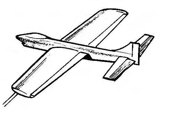
This publication presents a classic aerobatic model, simple in design and is designed specifically for the installation of the engine capacity of 3.5 — 7,2 cm3. In its design has taken into account the modest capabilities of asiacruise of the district level suit. The main materials used in the manufacture, the most common are pine slats, birch plywood, foam. The entire power frame is assembled on epoxy resin. To plant great upgraded motor “Comet-5A” or TC-4. It is possible to use motors of the type MDS-3,5 in aviagarant and MDS-25 with a working volume of 4.07 cm3. “Preteena” version of the model will be “rainbow-7” or “Talka-7”.
 
The fuselage is assembled from two symmetrical trusses-sidewalls. Each of them is glued together from strips and plywood security walls, which in the connection area of the wing to the fuselage strengthened by overlays. Cross set two frames and two polosamota of plywood. The tail part of the farm is connected by rails-spacers. The upper part of the fuselage fairing is a cut out of a foam type PS-4-40 melkosortnogo or packaging, and are covered with a thin Kraft paper on the casein or carpenter’s glue. PVA glue we used because it leaves streaks that are hard deleted. The rear part of the simulation of the cockpit canopy is cut from the packing foam and glued paper as well as the fairing. The fuel tank classic brazed steel, with additional internal wall. Tank volume — 100— 130 cm3. The hood the engine compartment is laminated of two layers of fiberglass with a thickness of 0,08 mm.
The single-spar wing model. The spar is formed by two shelves, and a wall of plywood or foam core PVC in the root and end parts of the wing and braces of strips of a cross section of 2×3 mm in others. Ending cut from foam and covered with paper or fiberglass. The ribs are made of veneer (or plywood). Each rib has a facilitating hole. The external console is placed a sinker weighing 20 g. the Flaps are made of packing foam with edging strips. Their lining is similar to the tail feathers. In the wing are mounted the rocking and traction control. The axis of rocking — of steel wire of diameter 3 mm Pull for a cord — stelisti wire diameter 0.8 mm, thrust, reaching for the pylon-flap — aluminum spokes with a diameter of 3 mm, rod elevators — from Reiki a cross section of 6×6 mm. the Shanks of the latter are made of steel wire with a diameter of 2 mm. the Axis of the suspension flaps from steel spokes with a diameter of 2.5 mm.
 
Basic dimensions of the pilot models
 
Main dimensions of the pilot models.


The fuselage
 
Fuselage:
1 — hood power plant, 2 — bars engine mounts (beech slats 10×13), 3 — internal overlay Board (plywood, s1,2), 4 — frame engine mounts (plywood, s6), 5 — fuel tank 6 — frame (plywood, s), 7 — fairing (plastic), 8 — upper stringer (pine, rail 4×4), 9 — a Board (plywood, s1,2), 10 — vertical struts (pine, rail 4×4) 11 — braces (pine, rails 3×4), 12 — tool insert of the stabilizer (plywood, s1,2), 13 — Kiel (foam, s5), 14 — rudder (foam, s5), 15 — tail wheel, 16 — rack (wire, diameter 1.5), 17 — stringer lower (pine, rail 4×4), 18 — horizontal strut (pine, rail 4×4), 19 — polosamote (plywood, s1,2), 20 — the bottom compartment (plywood ,2), 21 — wall vent (plywood, s1,2), 22 bottom plate (foam, s4). Section of the fuselage is increased.


Wing
 
Wing:
1 — ending (foam), 2, 5 — gusset plate (plywood, s2), 3 — strap pull output control (plywood, s2), 4 — rod (wire diameter 0,8) 6 — spar wall (foam PVC, s), 7 — front edge (pine, rail 6×6), 8 — shelf side member (pine, battens 7×2,5), 9 — rib (plywood, s1,2, or veneer aspen, Linden, s1,5), 10 — spar wall (plywood, s 1,2), 11 — strengthening beam flange (pine, rail 5×2,5), 12 — the lining of the wing (plywood, s 1,2), 13—strengthening of the junction of the front edge (pine, rail 10×7), 14 — rocking chair (made of anodized aluminum, s2), 15 — thrust (needle dural, diameter 3), 16 — loop the flap suspension, 17 — axis hinge flap (steel wire, diameter 2,5), 18 — bushing (tube, wrapped with thread and glued with epoxy resin), 19 — pylon flaps (brass, sheet s1,5), 20 —shelf T-shaped rear edge (pine, rack 5×3), 21 —rear flange (pine, rail 8×3), 22 filler flap (foam, s5) 23 — the front edge of the flap (pine, rack 5×3), 24 — trailing edge flaps (pine, battens 3×2), 25 the end of the flap (pine, rail 5×2).


Stabilizer and Elevator
 
Stabilizer and Elevator:
1 — ending (pine, rail 5×2), 2— the trailing edge of the stabilizer (pine, rack 5×3), 3 — the front edge of the stabilizer (pine, rail 5×2), 4 — filler stabilizer and rudder (foam, s5), 5 — loop hinges of the rudders, 6 — trim the end of the Elevator (pine, rail 5×2), 7 — reinforcing strip (pine, rail 5×3), 8 — the rear edge of the Elevator (pine, battens 3×2), 9 — the leading edge of the Elevator (pine, rake 5×3).

 
Main landing gear
 
The main landing gear.
 
Diagram of a control system of rudders
 
 
Diagram of a control system of rudders.


The mounting axis of the flap lies in the sequential Assembly of the entire node. To the workpiece axis in the middle of the soldered horn made of brass with a thickness of 1,5 mm. On axis to put on two tube-bushing (metal, plastic or twisted paper impregnated with epoxy resin on the spoke-mandrel). Right angle folded flaps leashes. A ready node is embedded in the cutout of the fuselage.
 
Then mounted the finished wing, is exposed along the axes and is attached with epoxy. To the rear edge of the wing tubes are glued-joints. In the last turn are hinged flaps. Loop for hanging rudders and flaps homemade or branded.
 
Chassis model — any design. On the fuselage you need to fix dural (plate thickness 2 mm) or wire (3 mm) stand with wheels with a diameter of 45 mm. the figure shows the easiest (by weight) of a variant with wing-mounted racks of spring wire diameter 3 mm. At the tail of the model cable clamp made of tin is attached to the crutch of the steel spokes with a cross-section of 1.5 mm. the Tail wheel with a diameter of 20 mm can be manufactured from PCB or polyamide.
 
The plumage of the model simple. Profile flat plate. The drawings show the stabilizer of packing foam with edging strips. He, like the Elevator, glued wide-adhesive tape-“Scotch”. On the rails of the edging “Scotch” must be ironed with the iron heated to a temperature of 100°C. the Adhesive layer thus polymerized and becomes resistant to fuel. The finished horizontal tail is not painted to save weight. In the same way are made the keel and the rudder. The latter is attached without hinges, at an angle. When assembling the empennage and chassis remember the weight and centering of the model. The excess weight of the tail affects the torque characteristics, and hence the quality of performance of maneuvers with sharp turns and high angles.
 
The close-fitting models can be the same type of mcalenney paper or Mylar film and combined the fuselage are covered with mcalenney paper, the wing covered in Dacron or thin nylon. Painting is performed with a nitrocellulose or synthetic dyes, after which the two-component model is covered with parquet or pentaphthalic varnish.
 
SKVORTSOV, the engineer

Recommend to read

  • THE MOTOR OUT…NAILS AND SCREWSTHE MOTOR OUT…NAILS AND SCREWS
    Before copiers that manufacture aircraft models in the Mel scale, often raises the problem of simulating a power plant with a radial engine. Offers an unusual method based on the use...
  • AND THE CURVE OF THEAND THE CURVE OF THE
    The starter on cars IZH 412, M-2140 and their modifications is attached by only two nuts, but they are very difficult to reach not only the usual key, but the mechanical head. So we need...