It is therefore very difficult to create a “milokumova” pilotage weight of 400…450 g due to insufficient thrust power plant with the engine working volume of 1.5 cm3 (a good model of this type can only be considered a happy exception to the rule). However, if you increase the flight speed (in this case, however, decreases the thrust for maneuvers) and to shorten kordovye thread, the model is able to perform aerobatic complex shapes. Unfortunately, the result of such changes, completely contrary to the desire of the only pilots to reduce the angular velocity of the flight “acrobat”.
Selecting the basic parameters of mass and specific load bearing surface of the device, which is automatically obtained with the approximate total area of the wing and stabilizer. After that you can proceed to layout the drawing pilotage. An airfoil is desirable to choose a blunt, with increased relative thickness. This profiling will provide some “dulling” of flight characteristics, but more importantly, the model will not accelerate in a dive and on the individual phases of flight in a strong wind.
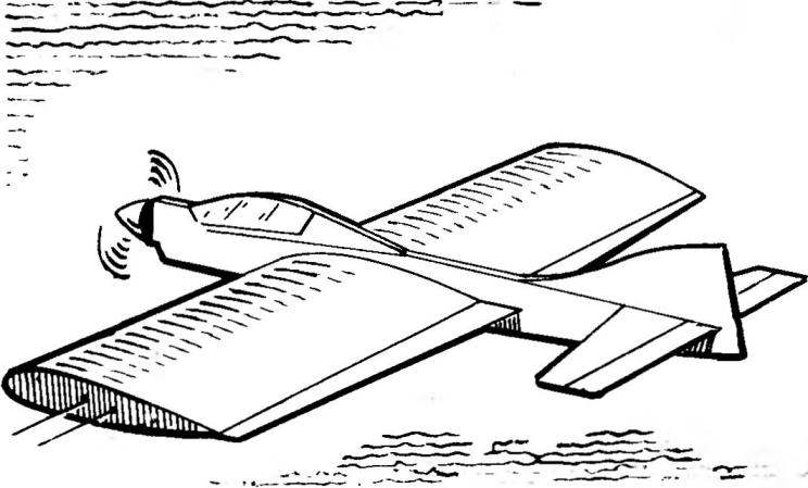
Training aerobatic control line model airplane.
Fuselage:
1 — jumper bow (Linden), 2 — beam engine mounts top (beech s 12), 3 screws M3 engine mounts (glued with epoxy resin in Motorama before mounting details 17), 4 — intermediate jumper (Linden), 5 — cheek motor right (plywood s2), 6 — jumper underwing (Linden), 7 — circuit receptacle (fake rack 12×2), 8 — lamp fairing (Linden), 9 — filler fuselage (foam stamps SS-4-40 packaging or melkosortnyj), 10 — stringers of the fuselage (pine slats 12×3), 11 is the covering of the tail (thin dense paper on the PVA glue), 12 — stabilizer cradle (pine rail 12×3), 13 — Kiel (Balto-Wai plate s3) 14 — the edge of the keel back (pine rail), 15 — boss of the fuselage rear (Linden), 16 — beam engine mounts lower (beech s12), 17 — cheek motor left (plywood, s1… 1,5), 18 — a lining under the foot of the crankcase remote (metal or plastic; can simultaneously be used to set the value of Vicosa the axis of the shaft out of the circle by 1 or 2°).
Wing:
1 — the flap (balsa plate s6; in the extreme case, the reproduced design is similar to the horizontal tail feathers), 2 — the ending (fake plate s5), 3 — the conclusions of the wires from the control cavity of the wing spring (spring rolls), 4 — flange front (Linden), 5 — rib (plywood s1 …1,5), 6 — polonaruwa, 7 — spar, 8 — casing of the Central section (plywood s1) 9 — Bob zakonopacheny (weighing about 30 g, lead), 10 — solitaire (Linden), 11 — edge of the rear, 12 — bracket synchronization of the action of the flaps (node templates). The wing — Mylar film of medium thickness.
Constructive wing profiles:
1 — edge front (Linden), 2 — overlay (lime; put only in the Central section), 3 — rib Central section (plywood s2), 4 — skin of the Central section (plywood with the direction of the fibers of the shirt along the wingspan s1), 5 — shelf side member (pine rack 7×3), 6 rail fixing of the axis of rocking of management (beech or birch; put only in the Central section), 7 — axis rocking (wire Ø3 OVS), 8 rocking control (dural or steel sheet), 9 — plate rear edge (Linden; to put only in the Central section), 10 — edge of the rear (pine rack 7×3), 11 — shelf end-to-end support (pine rail 9×2), 12 — rib (plywood s 1… 1,5), 13 — spar wall (foam stamps PHV; to put all mineralnych compartments).
A — wing section at the center section B — intermediate section.
Horizontal tailplane:
1 — ending (thick balsa), 2 — edge front (pine rack 5×5), 3 — edge of the rear (pine rack 5×3,5), 4 — strengthen the front edge (lime strap B5), 5 — filler stabilizer (foam stamps SS-4-40), 6 — plating (thick writing paper on the PVA glue), 7 — loop linkage steering, 8 — edge of the rudder front (pine rack 5×3,5), 9 filler wheel (melkosortnyj packing foam), 10 — edge of rear steering (Linden rail 2×2), 11 — ending rudder root (thick light balsa or basswood).
Fuel tank:
1 — supply pipe of the engine. 2 — body of the tank, 3 — tube filling and drainage (used for tank pressurization pressure tapped from the cavity of the silencer), 4 — the boundary of the gluing tank in the right compartment of the motor section of the fuselage.
Typically, the axis of the engine, the chord of the wing and the stabilizer arranged in the same plane. In practice, however, the horizontal tail it is possible to raise or lower the half-height of the fuselage — the model a light subclass of it does not cause a noticeable asymmetry of the behavior of pilotage in normal and inverted flight.
Quite a controversial point is the choice of the LENGTH of the forward fuselage. Many athletes believe that a good flight performance are ensured even at large offsets of the engine. However, as a rule, debaters take off their arguments after the first acquaintance with the flight characteristics Korotkevich devices. The fact is that a large removal of the engine is so big the moment of inertia of the model during aerobatics has not only significantly pererubat to get a little bit decent corners for “square” and “triangular” shapes, but also put up General sluggishness and lag of response of the apparatus to signals from the control stick. In principle, the skilled athlete-piloting would be able to control such a device, however, piloting skills, when to give the handlebars in the opposite direction to stop the rotation, coming soon. Note that this experience is very harmful, because after the transition to the model of heavy subclass will still have to develop new skills. This usually occurs when training on well-designed light pilotage.
The proposed model, the length of the bow is in the accepted limits. Of course, there was the temptation to build a machine with super short nose, but still such devices, unfortunately, have not won universal acceptance and is likely to be experimental. Our task is to create a reliable pilotage for training, working out the most complex elements of the AFCS, as well as for performances in the first competition.
The model design is quite traditional, and therefore does not require special explanation. The only thing I would like to tell you more — it’s about placing a sinker on the end rib of the right semi-wing. The fact is that improper placement can “screw up” even a very successful model. As you know, with sharp maneuvers pilotage rotates approximately along the axis passing through the center of gravity and, respectively, through the sinker. If you shift it to the back of the ribs, during the maneuver the nose of the model will begin to go to the center of the flight circle with the loss of a tension cord. And so every time, in every corner of the “square” or “triangular” shapes. The opposite effect occurs if the weight shifted to the front of the rib and is located before the center of gravity. Ideally, position it along the length of the model would be adjusted. But this increasing complexity is characteristic of “acrobats” heavy subclass.
In conclusion, a few words about vicose rudder. Traditionally, it is useful to reject it 8…10° in the direction of the “circle”. But, to understand the consequences of such improvements, to recommend her, to put it mildly, risky. The fact that a good model is simply not able to respond in normal flight, the discrepancy is small rudder. But in critical conditions, when the tension cords often not enough to reduce it due to the constant component of the lift force on the vertical tail is simply harmful. Count that emerged from the obedience model, without participation of the pilot to enter the right turn and restore the tension of the cord, can only desperate optimists.
I. GUREVICH,
the head of the circle
Recommend to read HANGER FOR FISHING LINES Rolled in a coil of hides, wire, fishing line conveniently stored by hanging on a hook. Nail the most simple but not the best option: in plywood or hardboard he did not last long. Much... WIRE SAWING In one of the rooms of the magazine was published a material "the Jigsaw for Plexiglas". Offer instead of nichrome wire to make a "electropulse" of two strands of nichrome. In this case,... 
 This cord pilotage has an excellent management system and has excellent maneuverability, which allows it to perform the most complex maneuvers. And most importantly – it never loses connection with the pilot due to robust tension cord at any point of the flight hemisphere. The design of this model is quite original and in many ways not consistent with accepted standards. In order to design such models, it is useful to get acquainted with the principles of determination of main parameters cord pilotage.