
 In recent times in the aviation modeling is increasingly being used by electric motors. This is understandable, their advantage in comparison with internal combustion engines is obvious: easy launch, precise control of the screw rotation speed, no exhaust, low noise.
 Now it created some interesting models of aircraft with electric motors. Made the first attempts to apply them on model helicopters.
In article V. Slepkova from Leningrad the possibility of making a model, in which electricity is supplied through the wires.
The choice of engine and the thrust calculation
The ability to create elektroperedacha (Fig. 1) first of all determined by the specific power of the motor. Easy and available engines there are a series of electric motors from vacuum cleaners, which with a relatively small weight and develop more power. The smallest of them is used in the electro Breeze. It weighs 430 g, and the capacity of short-term use can reach 75 watts, or about 0.1 HP of the same features and the popular internal combustion engine MK-17, however, when three times less weight.
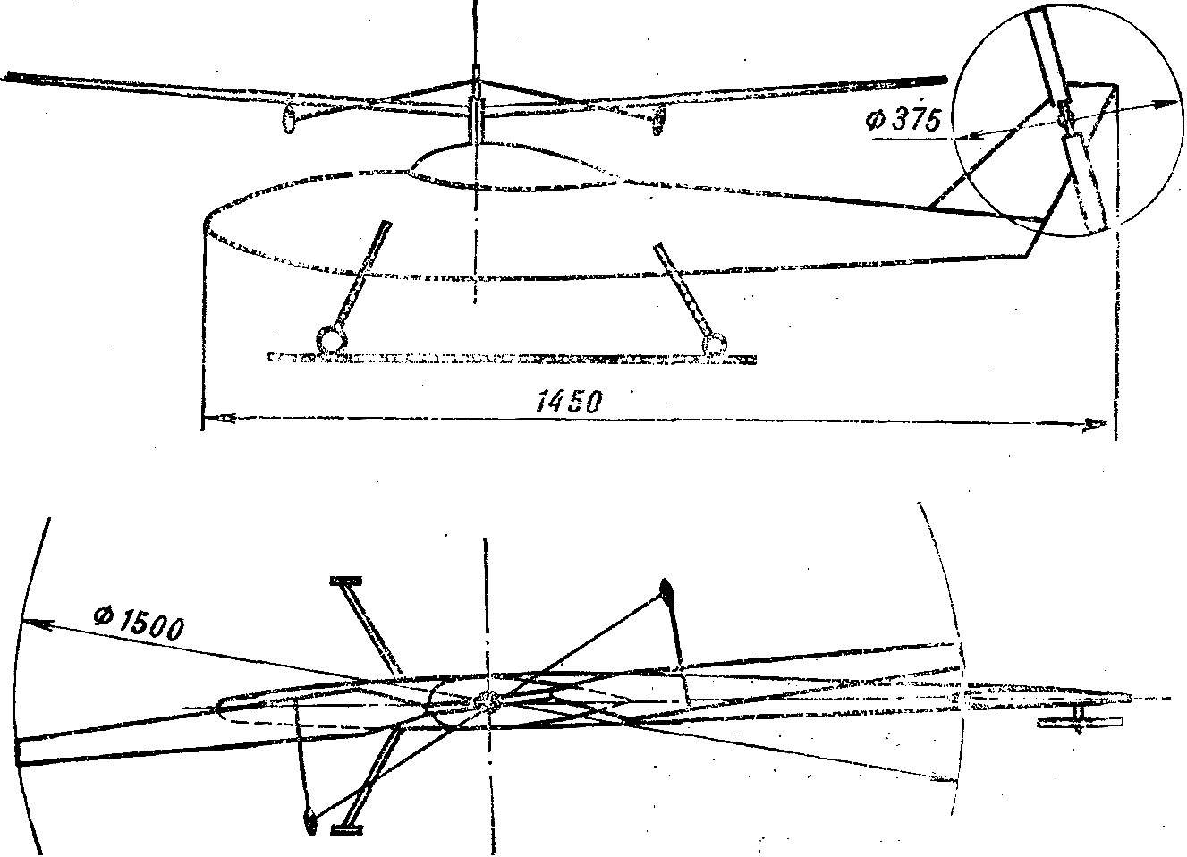
Fig. 1. Drawing models elektroversiya.
If test “Breeze” with a serial model aircraft propeller Ø 200 mm and 100 mm (Fig. 2) he developed a thrust of about 500 g, sufficient for the flight of an aircraft weighing up to 5 kg. But for a model helicopter requires a large energy supply.
In accordance with the formula N. Ye thrust of the rotor on hover is:
T = (33,25*NinDη0)2/3,
here: T — thrust, kg;
NB — power, HP;
D — diameter, m;
η — the relative efficiency of the rotor when working on site.
The value of η0 for the best model aircraft rotors reaches 0,65—0,7. The rotation of the steering screw, and fan losses in the gearbox also takes power. We assume that the proportion of it transmitted, the rotor will be 0,07 HP Choosing its diameter is 1.5 m, determine the thrust:
T= (33,25*0,07*1,5*0,65)2/3 = 1,73 kg.
Thus, for a model helicopter weighing 1.5 kg pull will allow flight at the “maximum” engine. Here we must note that in the horizontal flight, the required power is less than in hover mode. In addition, when the rise will have a positive impact effect of ground proximity. All of this suggests that the motor does not have to operate at maximum speed.
The choice of the model diagram
Currently in aviation, the bulk of the helicopters made by single-rotor with tail rotor, which became widespread thanks to the ease of management. Given that the model is manageable, it is best to use as the basis for such scheme. The variant of the drawing presented in figure 2.
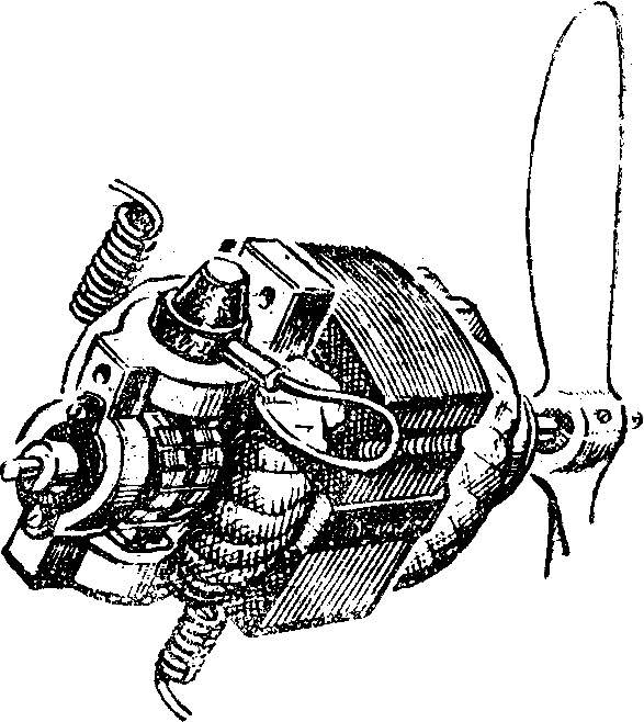
Fig. 2. Power motor “Breeze”.
For ease of fabrication and balancing bearing and tail screws are designed bladed. When you create any helicopter serious attention should be paid to sustainability. In the designed model it is provided with a stabilizing cargo, forming a kind of gyroscope. When the rotor loads that are installed on the blades tend to maintain the plane of rotation. In case of any deviation from the preset position the cyclic change in the angle of attack of the blades due to this that the aerodynamic force that returns the rotor to its original position. Changing the plane of rotation of the cargo with the swashplate, it is possible to control the flight of the model.
The main gearbox and transfer rotation on the tail rotor
To the rotor thrust developed estimated earlier, you need to choose the right gear ratio. The exact calculation requires knowledge of the load characteristics of the engine and the aerodynamic rotor. You can do an estimated calculation. Knowing the diameter of the poet, established in the tests on the motor shaft, and rotor, we can determine the gear ratio according to the formula:
iR = (RNV/R0)5/3,
where RNV is the radius of the rotor;
R0 is the initial radius of the screw shaft;
iR — gear ratio;
For RHB = 0.75 m; R0 = 0,1; iR = 28,8.
This ratio can be calculated, using two or three stages. If you select a double reduction:
I1 = Z1/Z2; i2 = Z3/Z4,
where Z — number of teeth of the gear unit. Taking Z1 = 10, Z2 = 100, Z3 = 17, Z4 = 93, get iR = 28,8. If, in practice, will not be able to pick up gear with a given number of teeth and there is a variance of +/-10% from calculated values, this will not lead to a significant decrease in rotor thrust.
Should seek to implement the reducer is easy and at the same time strong enough. To reduce the weight of large gears (Z2 = 100 and Z4 = 93) can be made of duralumin or of the PCB.
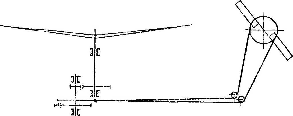
The transmission (Fig. 3) the tail rotor is the easiest to do with two pulleys Ø 60-80 mm: leading set on the intermediate stage gear, driven — on the tail boom. Connects the tape from nylon yarn Ø 0,8—1 mm.
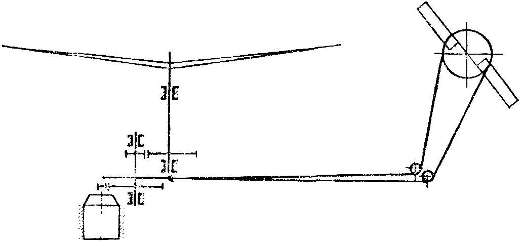
Fig. 3. Diagram of transmission model.
Model management
In the management model at the first stage, only two teams: change of engine speed and control on the course. The first is simple enough — using the included in the feed circuit of the variable resistor, for example, from the pedal of the sewing machine.
To control course it is necessary to change the pitch of the tail rotor. This can be accomplished by a miniature motor, for example, of the type DK-5-19 with gear. The last — timer (avtobuska for the camera).
After the first successful flights you can move on to more complex maneuvers. For this we need to add more . two servos to control the swash. Service flight “forward-backward”, “left-right”.
After the development of the model helicopter are plenty of events held here, which can be similar to the competition of these helicopters: flight, landing at a given point, etc.
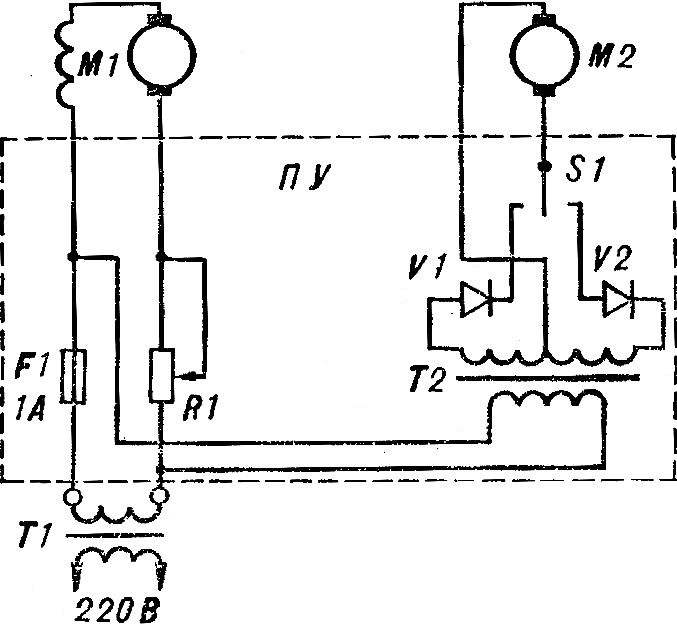
Fig. 4. Electrical schematic model:
M1 — power electric motor M2, a control motor PU — remote control.
In conclusion, a few words about safety. First of all you must carefully perform all of the connections between conductor elements as on the model and on the remote control. In addition, the latest be sure to install a fuse (Fig. 4) for a current of 1 A. Connect to the network preferably through a transformer. Finally, when preparing to start the machine, it is important to check the reliability of the entire system on earth. This tied the helicopter to the base, you have to run the motor in all modes, gradually increasing the speed of the rotor. Implementation of these basic requirements will ensure the safety of the flight.
Recommend to read
 CHRYSLER 300D
Walter Chrysler, linking his life with autostructure and occupy considerable positions in well-known US companies, dreamed, however, of creating your own car. With the help of three... RENAULT MEGANE — INSIDE AND OUTSIDE
French Renault Megane size class S. the French firm Renault was founded in 1898 by an enthusiast of the nascent car industry Louis Renault and eventually became the largest automobile...
