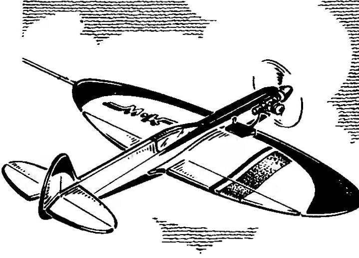
Design and piloting of the model fully understood from the drawings and therefore requires no further explanation. The only thing I would like to highlight the need for a preliminary calculation of loads on the cords.
The fact that the developed rudders and flaps at the maximum deflection angles can give such hinge moments of control efforts will be missed. Then the only solution would be to increase the “scope” of the swing and the distance between the points of suspension cord on the handle. The method of calculating the moments repeatedly cited in our magazine.
R and S. 1. Basic geometric data cord aerobatic models under the engine working volume of 2.5 cm3.
R and S. 2. Fuselage:
1 — uneven bars engine mounts (beech), 2 — front area, sheathed plywood with a thickness of 1.5 mm on the left side of the fuselage, 3 — boss (Linden), 4 — back boss (Linden), 5 — filler (foam), 6 — slats kit of the fuselage (Linden slats section 1,5×20 mm) 7 — trim (Linden, thickness 1 mm).
R and S. 3. Removable console wing:
1 flange (glued on a mandrel of four pine slats with a cross-section of 1×3 mm), 2 — Polonnaruwa (Linden, thickness 1 mm), 3 — rib (lime, 1.5 mm thick), 4 — shelf side member (pine, cross-section of 4×10 mm on a cone to the end of the console to the cross section 4×3 mm), 5 — root rib (ply, thickness 1.5 mm), 6 — root sheathing (Linden, thickness 1 mm), 7 — pin xation of the bracket on the fuselage, 8, the root rib of the flap (build from Linden slats), 9 — thread suspension components guards, 10 — front edge of the flap (pine, cross section of 3×5 mm), 11 — the rear edge of the console (pine, cross 5×12 mm), 12 — contour cropped, right-wing, 13 — different insights of cables, eliminating the hook carabiners cord when flying.
R and S. 4. Node connector of the wing:
1 — shelf side member console, 2 — container pins (fiberglass), 3 — screw MOH, with particular, 4 — glued the nut IA. 5 — fuselage, 6 power pins (Linden), 7 — the left boss (Linden), 8 rocking control, 9 — right boss (Linden).
R and S. 5. Keel:
1 — pin fixation (beech), 2 — power rib (Assembly of fake plates with a thickness of 1… 1.5 mm), 3 —long screw MZ fixing the keel on the fuselage, 4 — the outline of the keel (the bonding of the three strips 1×3 mm on the mandrel).
R and S. 6. Horizontal tail:
1 — thread suspension loop, 2 — loop stabilizer and rudders ‘*” height (gluing of three rails cross-section of 1×3 mm on the mandrel), 3 — the trailing edge of the stabilizer (pine section R tion 5×5 mm), 4 — the leading edge of the rudder (pine section of 3×5 mm), 5 — Central insert (Linden), 6 — connecting bracket rudder (wire OVS).
R and S. 7. Control scheme:
1 — rocking chair, 2 — rod, 3 — pylon flap, 4 — flap, 5 — pull rudder, 6 — pylon rudder, 7 — Elevator.
R and p. 8. Mounting the fuel tank in the right detachable console.
Recommend to read KEEP A — TRAIN! Clothespins (clothes and other) consist usually of several parts. From one: their manufacture will require only a steel strip. First she bent her middle round rod, then the ends of the... LACE FOR BRUSHES During painting operations, any pause — problem: where to put the brush? Help out a simple string, stretched between the ears buckets of paint. Neatly folded on it, the tool will quietly... Scroll back to top
 We offer cordovano-pilotando design developed in the model aircraft kraine Industrial syut Perm city under the leadership of K. Minkova. It is designed for engine KMD-2,5 and has a detachable wing, stabilizer and fin, which greatly simplifies the transport of the model and its repair. “Pilotage” is designed for those who have sufficient experience in modeling and wants to possess elegant and functional sports equipment.