
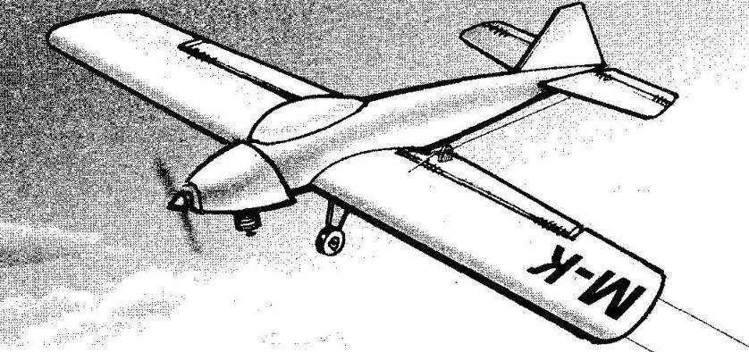
 Training control line model aircraft. This cord model training, as well as for Antonov an-designer, and for the Antonov an-pilot. The Creator will have to master the classical technology of manufacture and Assembly of the aircraft, and the pilot is to learn how to control it without fear of careless crop to decompose a model into its constituent elements.
The model is designed for the engine with working volume of 1.5 — 2.5 cm3 (MK-17, KMD-2,5, etc.) and is intended mainly for trainings in start up, simple aerobatics and landings. The model is quite durable and resilient, allowing you to manage it, even a novice pilot the model airplanes. The wingspan of the model — 800 mm, wing area — 23,6 dm2, weight — 800 g.
The fuselage of the model volume with a stacked frame with pine slats — spars and stringers, and five fake frames. Motor mount cut from beech plates 8 mm thick, tied to the spars and fuselage frame No. 1.
The Assembly of the fuselage easier to produce in the simplest slipway, which is a flat Board section about 150х30 mm where you marked the plane of symmetry of the fuselage and the axis of the frames. For mounting on the stocks of frames are used pieces of rails with cross-section 20×20 mm and a length of about 40 mm nails nailed to the stocks so that between each pair tightly included corresponding frame. The frames must be positioned so that their symmetry axis was vertical and aligned with the line of the plane of symmetry of the pile, and the grooves for longitudinal — parallel to the plane of the bench.
Next to fixed so the frames are attached with pins and clips (Bellevue or clerical) motor mount, longerons and stringers. In conclusion, in the rear tip of the fuselage the longerons and stringers are attached a fake boss and a keel, cut from the balsa plate thickness of 4 mm.
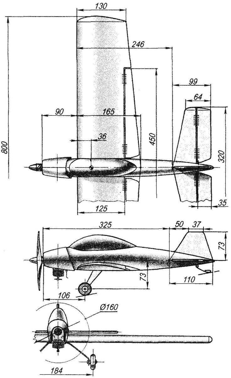
The geometric scheme of training cord model plane with an engine cylinder capacity of 1.5 — 2.5 cm3
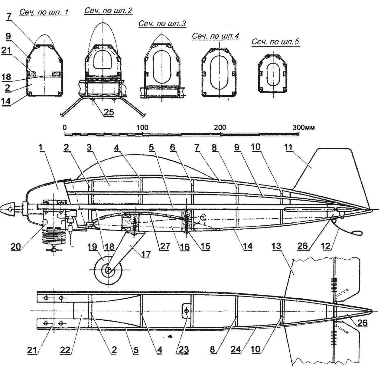
Design cord model (on the planned projection of the wing and the engine is not shown):
1 — hood (Vileika of epoxy resin and fiberglass); 2 — frame No. 1 (Linden, plate s5); 3 — fuel tank; 4 — frame № 2 (Linden, plate s3); 5 — spar of the fuselage (pine, rack 8×3); 6 — frame № 3 (Linden, plate s3); 7,9 — lateral stringers (pine, 6×3 rail); 8 — frame № 4 (Linden, plate s3); 10 — frame № 5 (Linden, plate, s3); 11 — the keel (balsa plate s4); 12 — skid (steel, wire EOD Ø2. 5); 13 — horizontal tail (balsa, plate s5); 14 — lower stringers (pine, rack 5×5 mm); 15 — wing mount screws (self-tapping screw Ø4); 16 — wing; 17 — spring chassis (aluminum, sheet s3); 18 — the bottom side of the fuel tank (Linden, veneer s2); 19 — wheel chassis (plastic, rubber, with an external diameter of 35 mm); 20 — engine cylinder capacity of 1.5 — 2.5 cm3; 21 — motor mount (beech, plate s8); 22 — jumper motor (beech, plate s8); 23 — boss wing mounting (beech); 24 — the covering of the fuselage (basswood, veneer s1,5); 25 — fixing screw spring chassis (a self-tapping screw Ø4); 26 — boss (Linden); 27 — base of the cradle wing (Linden, an interline interval s1,5)
After adjusting frame elements and a thorough check of the correctness of its Assembly and symmetry of all joints filled plasticized epoxy glue — if it is too thick, it can be slightly diluted with acetone or solvent № 646.
After curing the epoxy the frame is aligned with sandpaper glued to a flat plate, and then stick to it: the base of the wing cradle made of Linden veneer with a thickness of about 1.5 mm, beech boss with a hole diameter of 3 mm, intended for fastening the wing and the plywood (thickness 1 mm) at the bottom side of the fuel tank. Himself tank soldered tinplate with a thickness of 0.3 mm. the Filling and drainage tube are output through the left sidewall of the fuselage. Elastic supply pipe of the engine is passed into the engine compartment through the first bulkhead of the fuselage. Fixing the tank in the compartment is made using foam plates inserted between the tank and the frames.
Further, the frame is glued a 1.5 mm lime wood veneer, each of the plates whereby it is fitted to the frame in place, then secured with pins on the frames, and then the joints are filled with epoxy. Keep in mind that epoxy glue (even quite thick) has excellent fluidity, so apply it on the joints makes sense in several stages, waiting at the clearances of the joints absorbed another portion of epoxy. Ready vyshkurivaetsya fuselage and in the tail part is cut a groove under the stabilizer.
The horizontal tail is carved from a balsa plate with a thickness of 5 mm and sealed in a horizontal groove in the rear end of the fuselage. The Elevator (after painting the fuselage and rudder blades) is mounted to the stabilizer on the hinges-“eight” of the nylon thread, the blades of the rudder are connected by torsion of a steel wire in diameter 1,5 — 2 mm. Hog rudder is bent into the form of the letter “G” of duralumin strip with a thickness of 1 mm.
The final stage of finishing of the fuselage is the coating of two-component parquet lacquer, protecting the painted surface from dissolving its fuel.
Fiberglass engine hood wikiepedia the disc consists of three layers of fiberglass cloth on the epoxy binder. Blank cut from a foam plastic, puttied up the clay and covered with a release — supermonkey cling film used for packaging products.
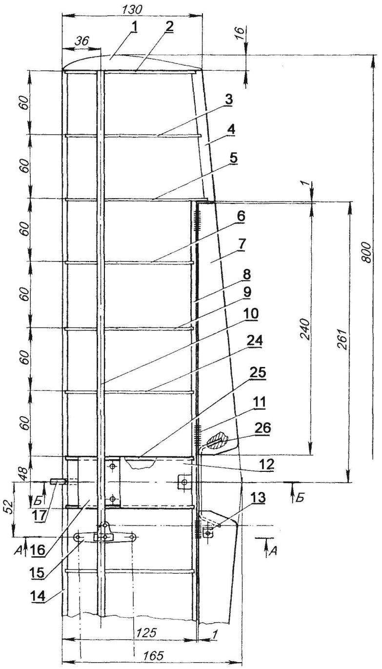
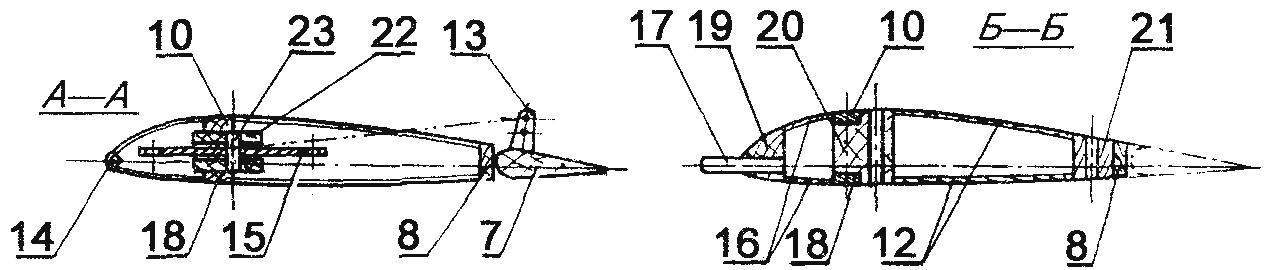
Wing design:
1 — ending (balsa); 2 — end rib (school line s3); 3,5,6,9,24 intermediate ribs (school line s3); 4 — rear flange (pine, rack 10×4); 7 — flap (balsa rail 40×12); 8 — rear wall (Linden, plate s4); of 10.18 — beam flange (pine, rack 8×3); 11 — loop flap (nylon thread); 12.16 to the lining of the Central part of the wing (Linden, an interline interval s1,5); 13 — hog control flap (duralumin, sheet s1,5); 14 — front edge (pine, battens 5×5); 15 — rocker control (duralumin, sheet s2); 17 — pin fixation wing (beech, rod Ø6); 19 -front boss (beech); 20 — the Central boss (beech); 21 — rear boss (beech); 22 — mounts the control arms of (beech); 23 — the axis of rocking of the control (steel, wire Ø3); 25 — the Central rib (school line s4); 26 — torsion (OVS wire Ø1,5 — 2)
After polymerization of the resin hood vyshkurivaetsya and covered with enamel. Used for mounting elasticity fiberglass shell — piece is securely “snaps” on the fuselage when the bonnet vents coincide with the semi-circular projections (heads of self-tapping screws) on the fuselage.
The frame is assembled from 14 wing ribs, sawn from school lines with a thickness of about 3 mm, pine dvuhromovo spar, lime rear wall, two balsa winglets, as well as from the front and rear edges.
Collect the wing is better in the stocks, consisting of a flat Board-base, which shows the planned surface of the wing with the axes of the ribs and spars, and the two rails along the front and rear edges; their thickness is selected so that the chords of the ribs, resting on these rails, and, accordingly, the plane of the chord of the wing, parallel to the plane of the stacker Board.
After the fit of parts and the temporary fastening them with clips and pins, the joints of the parts are filled with epoxy. On the axis of symmetry of the wing are glued beech, three lugs, one of which is used to fasten the wing under the fuselage using self-tapping screws, is secured to the rear of the wing: the second supporting spring chassis, is placed between the shelves of the spar; and the third, serving for the installation of beech pin-retainer with a diameter of 6 mm, in front of the wing. After gluing up the wing of the said bosses of the Central part of the wing is covered with a fake veneer 1.5 mm thick.
Assembled wing Marquesa (aligned) with sandpaper glued to a wooden rail with a length of about 1 m, and then between the shelves of the spar with epoxy glue fixed node, the control arms of consisting of two Linden bars, steel axle, a pair fluoropolymer washers remote and actually rocking, cut out of sheet aluminum with a thickness of 2 mm. Between the shelves of the spar flush against the end rib of the right wing is assigned lead a weight of about 30 g.
Next on the rocking chair fixed cables management that appear through the holes in the balsa ribs to the wing tip.
The finished wing is fitted by a Mylar film thickness of 25 µm with the help of glue “Moment” and the usual iron by standard techniques, often described in the journal “modelist-Konstruktor”.
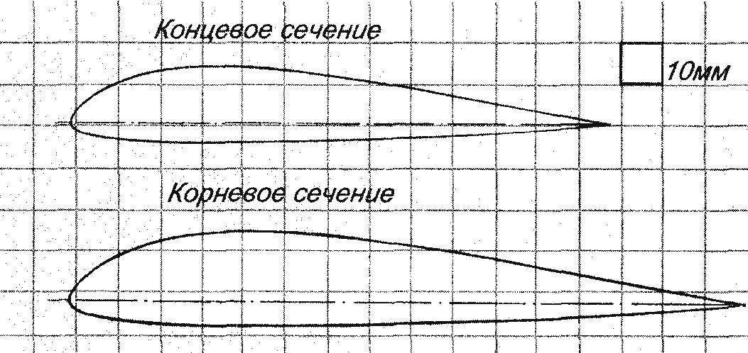
The theoretical contours of the airfoil
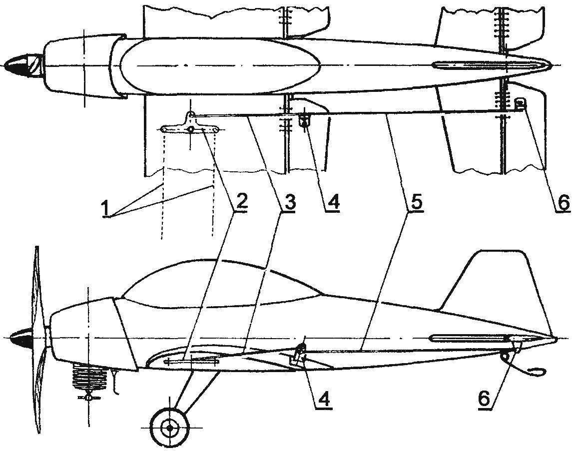
Control system model:
1 — wire control; 2 — rocking chair; 3 — control rod flap; 4 — hog of the drive flap; 5 — pull Elevator control; 6 — horn of Elevator drive
Flaps — seleblitie; after finish and color, they are pivotally fixed to the wing with hinges-eights of the nylon thread. When installed on the wing left and right flaps are connected by torsion of a steel wire with a diameter of 2 mm. Pylon actuator flap is bent from aluminum strips with a thickness of 1,5 mm.
The wing is attached to the model using beech pin-lock with 6 mm diameter installed on the axis of symmetry in front of the wing, and self-tapping screws with a thread diameter of 4 mm in the rear part of the wing. To provide a threaded connection, improved durability, in beech, the PIP makes sense to paste a simple plastic dowel.
Chassis model spring with plastic rubber wheels with a diameter of 35 mm, is borrowed from children’s toy car. The spring is cut from a sheet of aluminum 3 mm thick, on the wing it is attached using two self-tapping screws with an external diameter of 4 mm. In beech, the boss also need to glue the plastic dowels.
Skid, bent from 2.5 mm steel wire grade optical fiber, mounted in the tail lime lug with epoxy glue.
The model flies well on cords, length 10 — 12 m. For the first flight of the recommended alignment is 15 — 20% these values provide the best combination of stability and controllability.
I. SOROKIN
Recommend to read
 DISTANCE ON THE PROGRAM
Practice starts in the competition boat-"bramahadev" convincing evidence that until today the question of establishing a simple and reliable device for shutdown of main engines after...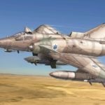 LION OF THE DESERT
Israeli fighter "Kfir". In 1967 the French President Charles de Gaulle banned the supply of arms to Israel. This decision was a response to the Israeli attack on the neighboring Arab...
