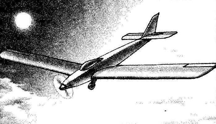
 Glider with motor Speed-600. With the development of gliding enthusiasts of this type of aircraft have sought to combine the merits of soaring flight and motor. The fact that non-motorized glider under favorable conditions, although it may stay in the air for dozens of hours flying during this time hundreds of kilometers, however, the vagaries of the weather can at any time force it to land in most unsuitable place for it.
Here is something to help the pilot can come to a small engine allowing the machine does not depend on the wind and updraft. Such hybrid aircraft, dubbed the “glider”, has been done—as professional designers and designers-enthusiasts.
Similar created gliders and model airplanes with relatively low-powered internal combustion engines light RC vehicles with the high aspect ratio wing, able to climb in the motor mode and make subsequent long soaring flights. However, model internal combustion engines for re-runs was, unfortunately, not able.
Model gliders survived his second birth with the advent of light and powerful electric motors and large-capacity batteries, which provided these aircraft steady climb and a long flight later, in which it was possible to repeatedly turn on and off the motor, allowing how to find ascending air flows, and to choose the most suitable place for planting.
Today many companies produce model to model airplanes ready devices of this type, or sets of parts and equipment to assemble them, but for readers of the journal “modelist-Konstruktor” this is not the way—we offer them to make such elektrootoplenie on their own— in principle, it is not more difficult than any other radio model.
Aerodynamic design of elektrootoplenie — low with straight wings of large aspect ratio with a relative profile thickness 14 percent.
The basis of the power plant of the machine—motor type SPEED-600 with electronic switch—this feature allows you to commutate the motor in flight. In principle, one can use an engine without such a device will only have to install on another model of the steering machine to drive a homemade mechanical switch.
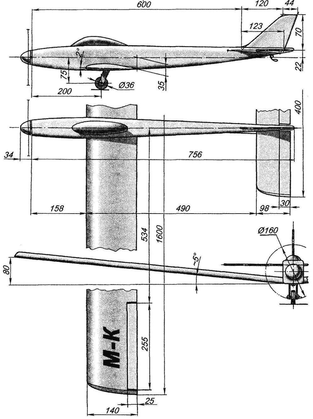
Geometric diagram of elektrootoplenie
For remote control elektrootopleniya uses three channels— roll (ailerons), pitch (Elevator) and the commutation of the motor. In principle, it would be possible to use also the rudder, but in flight it usually is not used.
In the manufacture of model widely used a homemade foam panels — stock material are of a thickness of 3 mm were cut from the ceiling foam plates. The thickness of the latter is usually about 6 mm, so they had to “dissolve” into two parts with a handmade electrothermography — smooth wooden planks, over which at a height of 3 mm (this distance was determined by the thickness of the two strips of heat resistant material) stretched nichrome wire, glow or electric shock. For the selection of required temperature of heating was used Latr—transformer with adjustable voltage. Optimum can be considered the temperature at which the surface section of the workpiece was obtained as if vitrified.
The fuselage of the model has a rectangular cross section with rounded corners.
In the fore part are two frames from plywood thickness of 3 mm with a cut in them round holes, the diameter of the motor. The rest of the frames—sandwich, each glued with epoxy two 1 mm plates of fake veneer and foam filler with a thickness of 3 mm. Sides of the fuselage also glued the fake veneer and foam—in contrast to frames the veneer to the foam filler is glued only on the outside.
Gluing the “sandwich” is made on a flat Board is coated with “epoxy” and put together the foam and lime blanks laid out on it and pressed with the help of goods (plastic bags filled with sand) same Board. Between the boards and the blanks were laid plastic film—otherwise you can get “sandwich” of tightly glued pairs of boards, and so we need panels.
After you cut from “sandwich” pieces of the sidewalls of the fuselage, each of them is contoured by a pine laths with section mm 5×5—this operation was carried out at the slipway using the same epoxy glue. The slipway is a flat Board with the depiction of a contour of the sidewall of the fuselage and hammered along the contour of nails with a diameter of about 4 mm by 50-60 mm.
From the same blanks-“sandwiches” were cut top and bottom panels of the fuselage.
Assembly of the fuselage was made in two stages. First—preliminary (dry) Assembly with the use of rubber rings, pins and paper clips—this phase tests the accuracy of manufacture of parts and their conformity to each other and conducted mutual fit, the frames and cut the holes for the connecting wires, remote control equipment for traction Elevator drive.
Further details consistently prokatyvalis epoxy glue and with the help of rubber bands, clips and pins were fixed on the appropriate places. After the Assembly, while “epoxy” is still not cured, the fuselage was checked for symmetry, lack of warps and twist.
After polymerization, glue the corners of the fuselage was round and its surface was visceralis and podsalivanii.
Horizontal tail consists of a lime frame and foam fill. The profile of the stabilizer is flat, with a rounded front and pointed rear edge. Blade pitch control—babesave, among themselves they are connected by a torsion bar, bent from the segment of the dural knitting needles with a diameter of 2 mm, and with the stabilizer are connected by loops of nylon tape. On the left of the blade fixed steering hog control, bent strips of duralumin with a thickness of 1 mm.
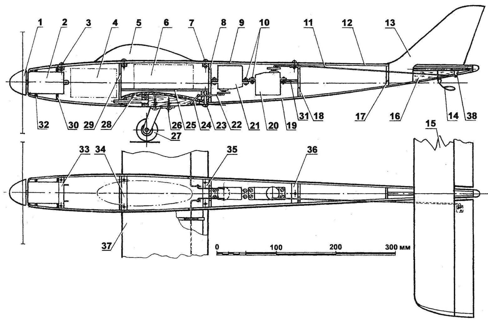
The layout of elektrootoplenie:
1—propeller spinner; 2—motor type Speed-600; 3, 7 — fastening the top panels of the fuselage (self-tapping screws Ø2. 5); 4—compartment remote control equipment; 5—lamp; 6—accumulator compartment; 8, 17, 18,29—frames (“sandwiches” of foam s3 and two layers of fake veneer s1); 9—upper removable fuselage panel (“sandwich” of foam s3 and one layer of fake veneer, s1); 10—mount servos (screws and nuts with thread M2,5); 11 —rod Elevator drive (aluminum, wire Ø2. 5); 12—upper removable fuselage panel (“sandwich” of foam s3 and one layer of fake veneer, s1); 13—keel (balsa plate s3); 14—crutch (the wire Ø2 OBC); 15—horizontal tail; 16—boss (balsa); 19—the lower panel of the fuselage (a”sandwich” of foam s3 and one layer of fake veneer, s1); 20—steering machine of the Elevator drive; 21—steering machine actuator Aileron; 22—thrust actuator Aileron (aluminum, wire Ø2); 23—wing mount (self-tapping screw Ø4); 24—the lever-torsion bar actuator Aileron (aluminum, wire Ø2. 5); 25—the bottom compartment of the batteries (a”sandwich” of foam s3 and two layers of fake veneer s1); 26—mounting rack chassis (a self-tapping screw Ø4); 27—wheel chassis Ø36.; 28—the cradle for the wing (Linden, veneer s2); 30, 32—front frames (plywood s3); 31 —base servos (plywood s4);33,34,35 and 36 of the cross member (Linden, 5×10 rail); 37—wing; 38—the horn of the Elevator drive (duralumin, s1)
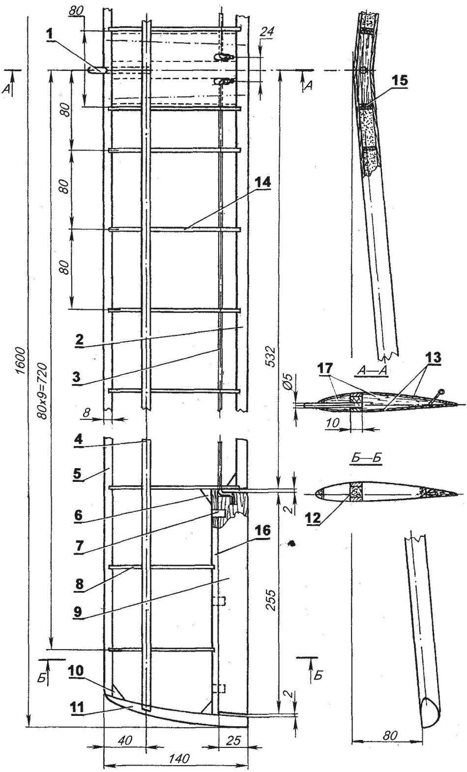
Layout of the wing (Mylar wing skin is not shown):
1 —a connecting pin (beech, rod Ø5); 2—trailing edge of the wing (pine, rail 3×12); 3 —the lever-torsion bar actuator Aileron (wire Ø2 OBC); 4—shelf side member (pine, rail 4×10); 5—the leading edge (pine, rack 10×12); 6, 10—reinforcing the scarf (lime); 7—hinge Aileron hinges (nylon webbing); 8—short rib (a”sandwich” of foam s3 and two layers of fake veneer s1); 9—Aileron (balsa); 11—ending (Linden); 12—filling spar (foam); 13—a lining of the Central part of the wing (Linden, veneer s2); 14—rib (a”sandwich” of foam s3 and two layers of lime veneer, s1); 15—strengthening of the Central rib (Linden, veneer s2); 16—the wall (lime, rake 5×10)
Horizontal tail:
1 — blade rudder (balsa); 2—Central jumper (Linden, plate s5); 3—torsion (aluminum, wire Ø2. 5); 4—filling (foam); 5—loop hinges of the Elevator (nylon webbing); 6—the leading edge (pine, rail 5×6); 7—wall (a pine, a rack 5×5); 8—reinforcing the scarf (lime); 9 — ending (Linden)
The rudder is celebarty, it is cut out from plates with a thickness of 4 mm. the Profile is also flat, with a rounded front and pointed rear edge.
After installation on the fuselage of the fin and horizontal tail, as well as pre-installation of motor, battery, receiver and servos makes sense to estimate the location of the center of gravity of the fuselage Assembly. In principle, it should be located around 25-30% of the chord of the wing, otherwise will either have to lighten (load) the tail, or, in extreme cases, to shift forward or back the wing relative to the fuselage.
The wing of the glider is asymmetrical biconvex profile with relative thickness of 14%, which has good bearing properties and low stall speed. The wing has a pronounced V-shape—she is about 5 degrees relative to the horizontal; the installation angle of the wing is 2 degrees.
Structurally, the wing consists of two symmetrical halves joined along a symmetry axis through the pine panels and cladding veneer the Central part.
The wing spar—dvukhpolosnykh, with pine shelves section 10×3 mm, inter-shelf space is filled with foam. Pine also made the front and rear edges. The wing ribs were cut from the same sandwich blanks, and frames of the fuselage—they also consist of two outer layers of phony veneer 1 mm thick and the foam plate 3 mm thick.
In the Central part of the wing spars right and left polycrylic connected to each other with pine inserts, on the axis of symmetry is glued fake boss it will be further fixed landing gear beech and pin fixation of the wing.
Mount the wing to the fuselage is a couple of screws with M5 threaded under them to the wing are stuck with two of the dural sleeve with an inner diameter of 5 mm, and in the fuselage two threaded bushings are threaded M5.
The ailerons are cut from balsa wood; on the wing they are mounted with loops that represent the segments of the nylon braid. The lever-torsion bar actuator Aileron bent from a steel wire in diameter of 2 mm.
The wing and horizontal tail tight fitting Mylar film on standard model aircraft technology, using type of glue BF-6 and a small plate.
Chassis elektrootoplenie—single column, with rubberised plastic wheel with a diameter of 36 mm, borrowed from children’s toys. Front—sheet of aluminum 2.5 mm thick; on the wing it is secured by two screws-tapping screws. In the rear part of the fuselage-mounted skid, bent steel wire with a diameter of 2 mm.
In conclusion, several practical recommendations.
On the wingtips it makes sense to install additional supports—two semi-circular arcs of duralumin wire diameter 2.5 mm—they will protect the trim and the ailerons during landing.
In the end, it is necessary to finally clarify the alignment of elektrootoplenie. As mentioned—she needs to be 25-30% of the chord of the wing.
Before the flight we recommend to practice in the management of elektrootopleniya by not raising it in the air. In windy weather, hang the model on a durable filament fixed in the centre of gravity on the crossbar of the horizontal bar, a tree branch or on the end of the inclined installed a three-meter rack, and try to direct elektrootopleniya—enter it into the roll and out, to make cabriolet (perk) or to dive.
Launching a glider is best done by guard rails or using rubber cord-shock-absorber. In the extreme case the model can be run with it. It should be borne in mind that the supply of power from the motor is small and, accordingly, the rate of climb of the model is low, so no need to wait for the mind-blowing maneuvers. But the possibilities to “steer” a glider in search of ascending currents, you will abound.
You need to consider that in the absence of a rudder of the model makes a u-turn with the introduction of it in the roll and the simultaneous translation of the handle of the Elevator control “on”as it enters the bend; it remains only to wait for the desired course, to fend off the roll with simultaneous translation of the handle of the Elevator control in neutral.
The landing must be made against the wind. In principle, ambulancewoman model in planning can sit down and by yourself—just bring it to the landing pattern, to bring to the height of 2-3 meters and to install control knobs in the neutral position. However, it is preferable to plant elektrootoplenie with the direct participation of the pilot, whose task is the removal of the model on planting rate and after reaching its height of 1 meter—transfer apparatus in horizontal flight to withstand the loss of speed until landing. Followed by a smooth increase of the angle of attack of the model until the beginning of parachuting. The perfect fit would be the case if the moment of touching the ground the wheel will coincide with the start of the parachuting.
I. KARAMYSHEV
Recommend to read
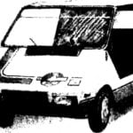 “RUTA”-AUTOROLLER
Our laboratory autocostruzione the House of young technicians stand on the court readers of the magazine "M-K" design of a micro-car, only. This time it's "RUTA" — crew training car. ...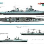 THE SOVIET “LIGHT HEAVYWEIGHTS”
The state of the Soviet cruise fleet in the early 30-ies of the last century can hardly be described as sad. The last ships of this class light cruisers of "Svetlana" have not been...
