 For many school model aircraft clubs create room flying models is the only available form of modeling. Judge for yourself: the season of the competition model, as a rule, coincides with summer vacation, and autumn, winter and spring start model is quite difficult weather conditions. At the same time any sports or Assembly hall is a great arena for competition in the class of low-speed models with resi-nomotion. The design of the latter — the process is no less fascinating.
We offer the simplest room model with careful execution can stay in the air for about five minutes.
Before you start working on making the model, you need heavy paper to draw a detailed and accurate Plaz (drawing full size): it will facilitate the implementation of all subsequent operations.
First of all, the Assembly of the fuselage. It is the Foundation of rake made of reeds, Chia or durable and thick rye-straw. In the latter case, to ensure the strength should assemble the fuselage of the two straws inserted into one another by spreading the glue. During Assembly of the nodes of the model it is recommended to use cycrin or one of those quick-drying glues, which are called “Second”, “Super”, “Moment”.
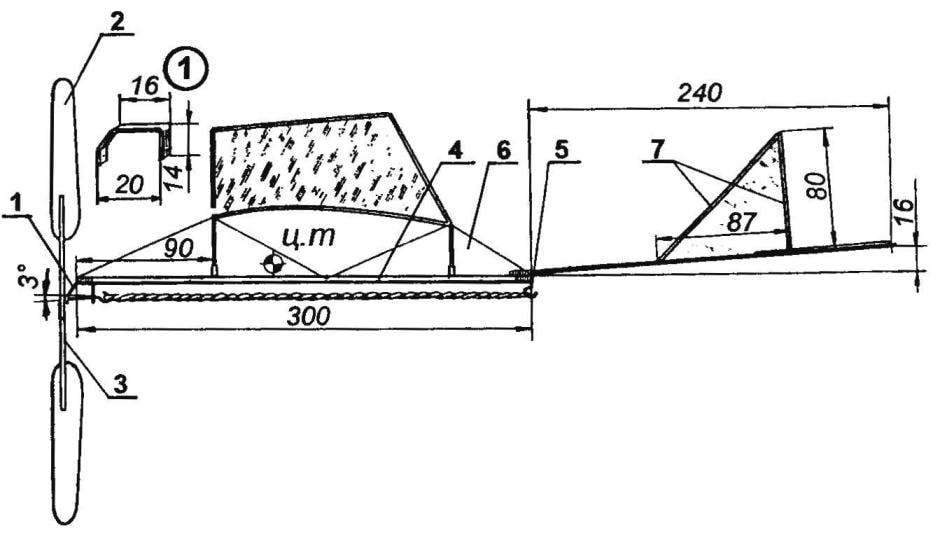
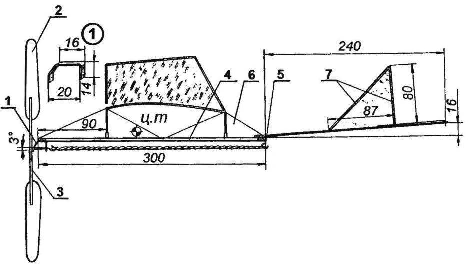
The shaft bearing of the propeller is a strip of aluminum with a thickness of 0.3—0.5 mm, bent in the form of the letter L; the fuselage is a thread with subsequent impregnation glue. It should be borne in mind that Vegas of the screw shaft to the right is 8 degrees and down 3 degrees.
At the rear of the fuselage rails with a thread and a glue secured to the hook for engagement of the rubber motor, bent from a steel wire in diameter of 0.5 mm, and the sleeve mounting the tail boom (tube is made of straw with a length of 12 mm). To install the wing on the fuselage rail fixed (thread and glue) straw tubes with a length of 5 mm.
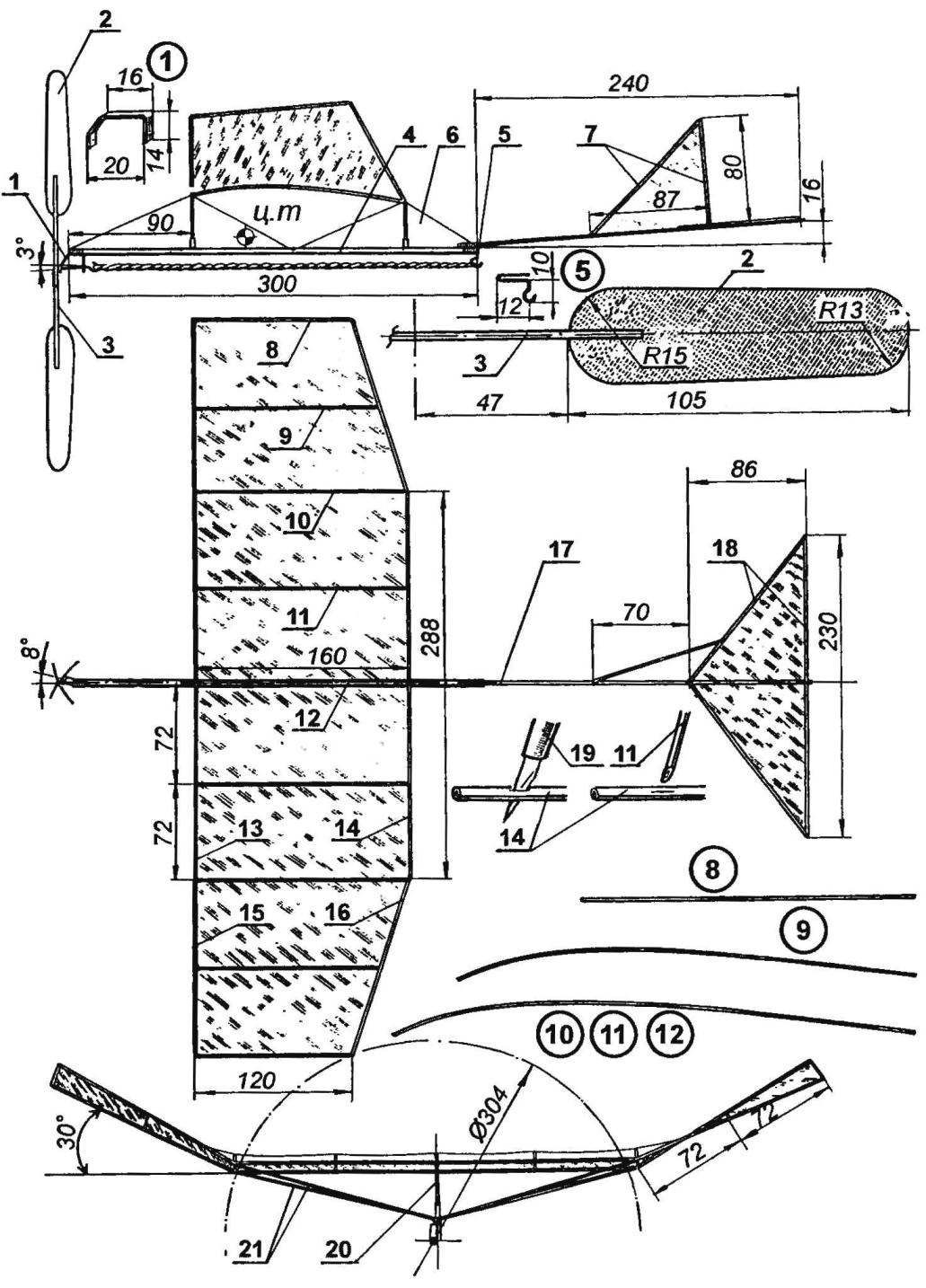
Room rezinomotornaya model airplane:
1 — shaft bearing of the propeller; a 2 — blade propeller; 3 — hub of the propeller; 4 — the rake of the fuselage; 5 — hook attachment of the rubber motor; 6 — brace; 7 — the elements of the frame of the keel; 8 to 12 — rib; 13 — the leading edge of the wing; 14 is the trailing edge of the wing; 15 — front edge of the console; 16 — rear edge of the console; 17 — tail beam; 18 — frame elements of the stabilizer; 19 — cutter; 20 — front wing mounting; 21 — wing struts
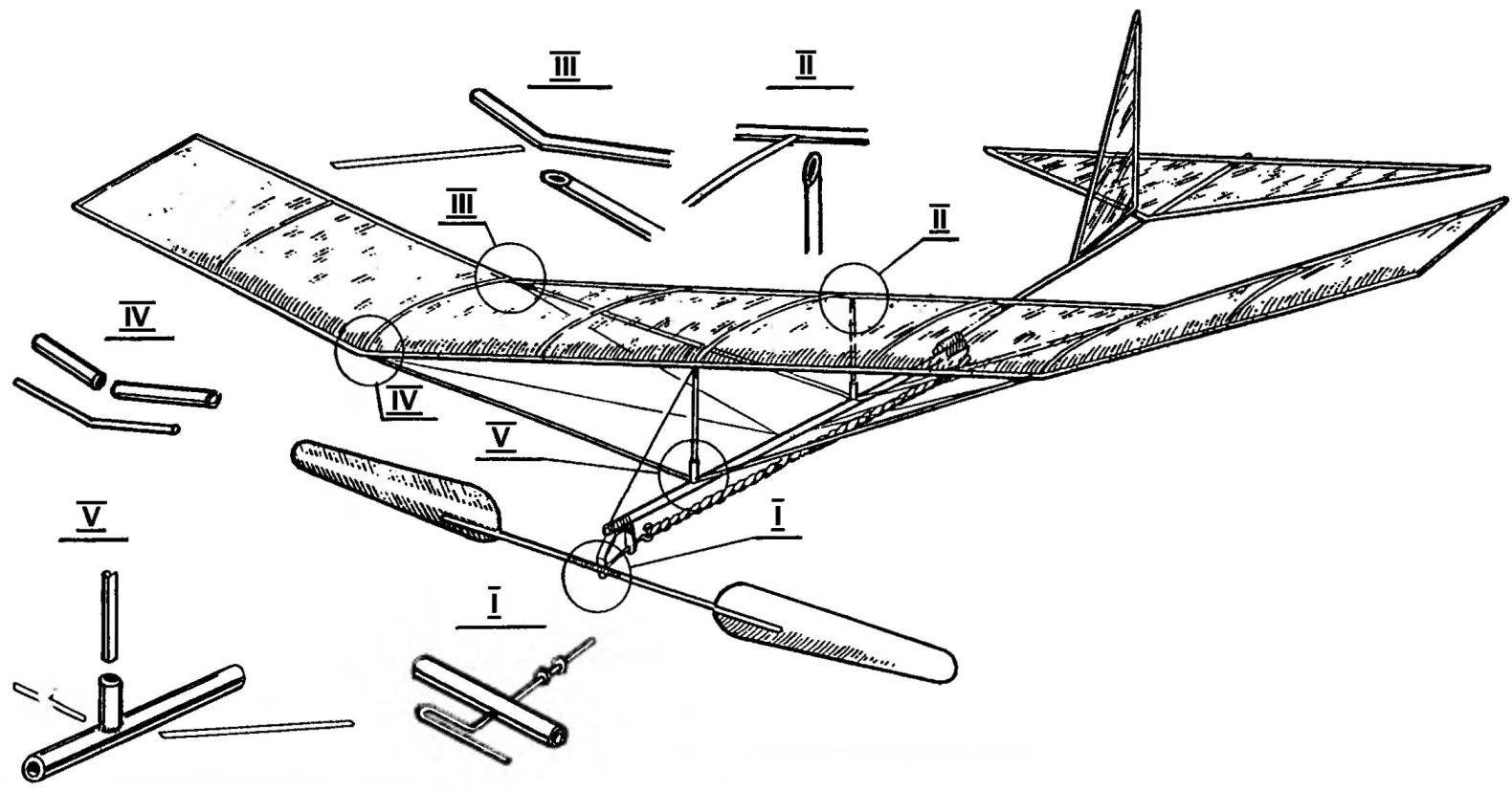
The main docking room model
Wing Assembly begins with the mounting of the center section of a rectangular shape. For edges and braces are used pieces of straw with a diameter of 1-1,5 mm. Prior to Assembly of the workpiece should be straightened out — this can be done by heating the straw in the cylinder is included an electric lamp. Rib straw bend also with the lamp — they are given a profile according to the drawing of the wing. It is necessary to ensure that the curvature of the ribs was strictly the same.
During Assembly the ends of the ribs are sharpened and inserted into holes pierced by the cutter in the front and rear edges of the wing. The connection of the straw parts before gluing slightly stripped.
Console going the same way as the center section. Connection consoles and center section is made using curved segments aluminium or steel wire.
The wing set on the fuselage with struts, fixed by glue in a straw bushings on the fuselage rail. Additionally, the wing is enhanced by the struts and braces of thin nylon thread.
The frames of the stabilizer and fin going out of the straw pieces with a diameter of 0.5—1 mm and are fixed on the tail boom thread and glue.
The finished model is covered with condenser paper.
The hub of the propeller is carved from a chiy or two placed one inside the other straw billet; the outer hub diameter is 4-5 mm. the screw Shaft is bent from a steel wire in diameter of 0.5 mm. Blades cut from tough Mylar film or heavy paper is inserted in rassay in the hub of the screw is made at an angle of 45 degrees to the plane of rotation of the screw, and fixed by glue. To increase the traction of the propeller, the vanes attached to the convex form.
The rubber motor of a model consists of a pair of strands cross section 4×1 mm. To improve operation of the rubber motor should lubricate it with castor oil.
I. KARAMYSHEV
Recommend to read
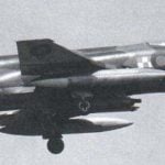 GHOSTS IN THE ROYAL SERVICE
In the beginning 1960-ies to the leadership of the British Navy faced the problem of replacement fighter aircraft "sea vixen" (Sea Vixen) more modern machine. First, the sailors wanted...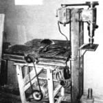 AND FOR THE JOINER AND CARPENTER
Please tell about your Hobbies. Like to create: to create with their hands the things that enhance the comfort and beauty home. I especially like working with wood — carpentry,...
