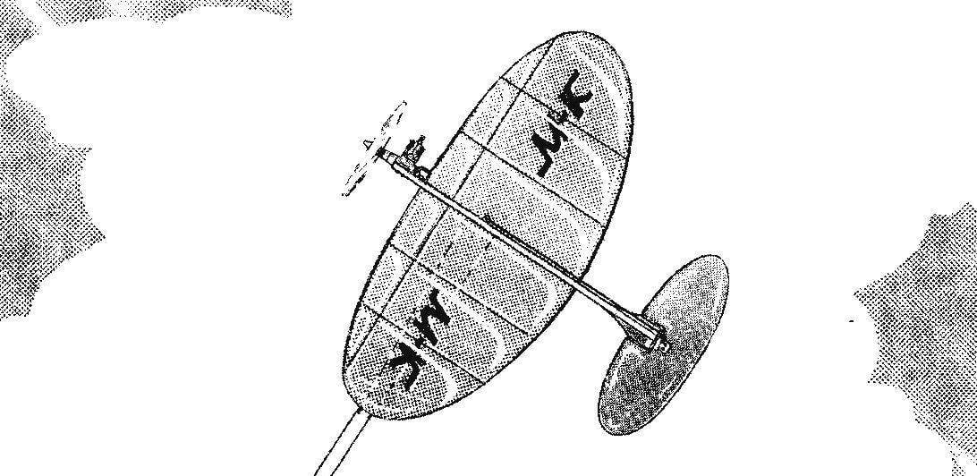
 Universal control line model aircraft. The design “Teardrop” models for air combat — have occurred in several stages. In fact, immediately, in one step to create obedient to the pilot model was not possible, believe me, anybody. As a rule, first designed and built a simplified model, which practiced its concept, geometric parameters, the controllability and stability of the flight. Further, according to the results of test flights made necessary modifications, and then creates a second version of the model in which the basis is all the best from the first. Sometimes the model is good, but often for the second stage follows the third…
However, we hope that you are lucky — after all, before the drawings of this model have appeared in the journal, the designer has passed these three stages of its creation.
The final version of the model to air combat proved to be very successful. He has a good combination of stability and controllability and is therefore suitable for beginners as “fighters” and experienced “only pilots”. The latter, incidentally, doing a slightly modified version of the “Ellipsoid” with the keel, pilot lamp and two-wheeled chassis.
“Teardrop” is performed by the standard to “bouzouki” scheme is a flying wing with the recommendations in the tail boom all-moving stabilizer. Design made using balsa, basswood and pine.
The wing is an oval irregular shape of less curvature in the front and more rear. The frame consists of dvuhromovo spar with shelves made from pine slats with a cross-section 11×5 mm and a wall from lime plate 3 mm thick. the Forehead of the wing with the filling of the packing foam.
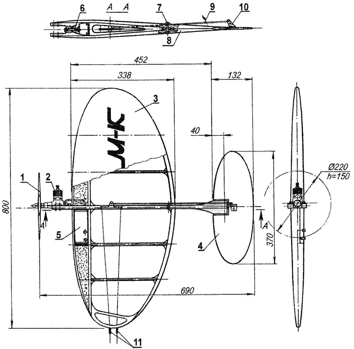
Design model for air combat engine KMD-2,5 (in a side view the engine is not shown):
1 — propeller (Ø220, h = 150): 2 — engine KMD-2,5; 3 — wing; 4 — all-moving stabilizer; 5 — fuel tank (capacity 120 cm3); 6,7 — screws M3 attaching the wing and fuselage; 8 — fuselage; 9 — control rod (dural needle Ø3); 10 — hog control stabilizer (aluminum s2); 11 — grommets control wires (spring steel wire Ø0,5)
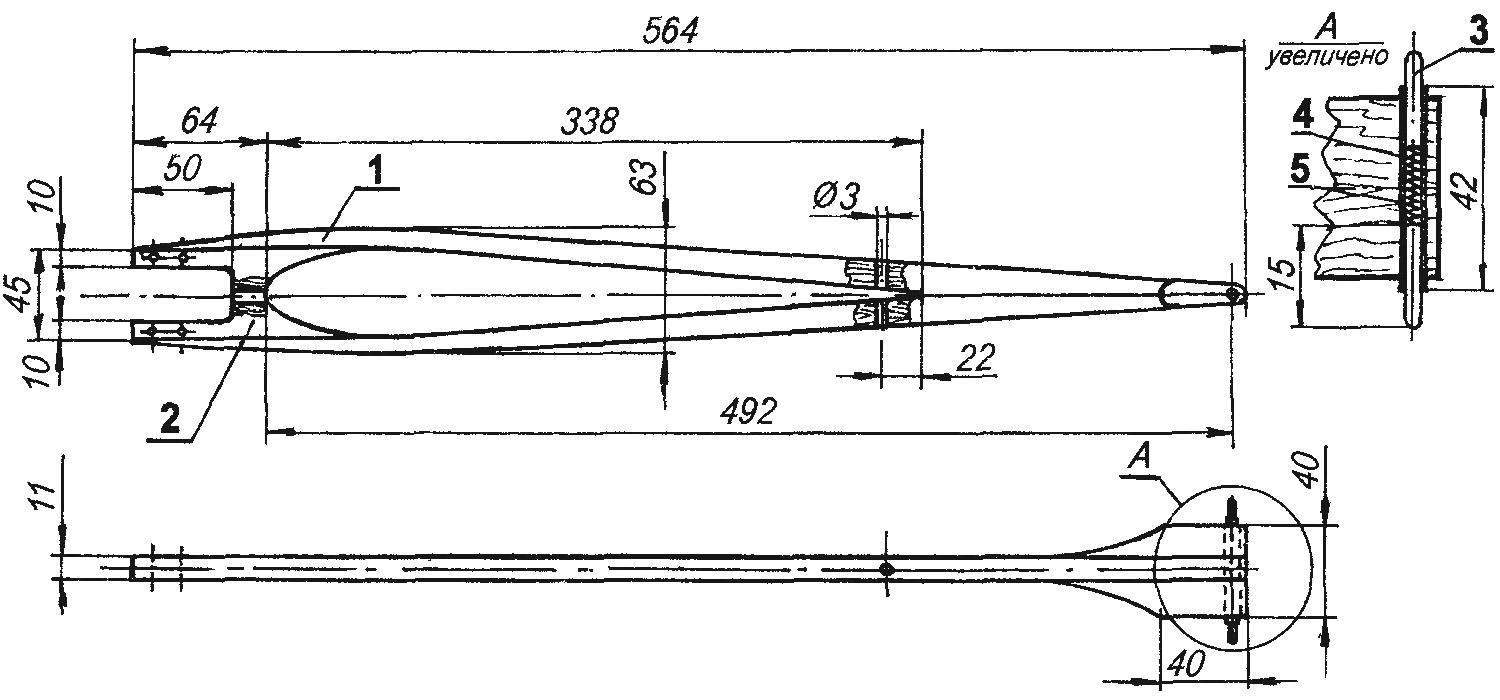
The fuselage of the model:
1 — pad (pine, rail 20×11); 2 — engine mount (beech, plate s11); 3 — driveshaft (steel wire Ø3); 4 — spring; 5 — Bush (plastic tube 3×0,5)
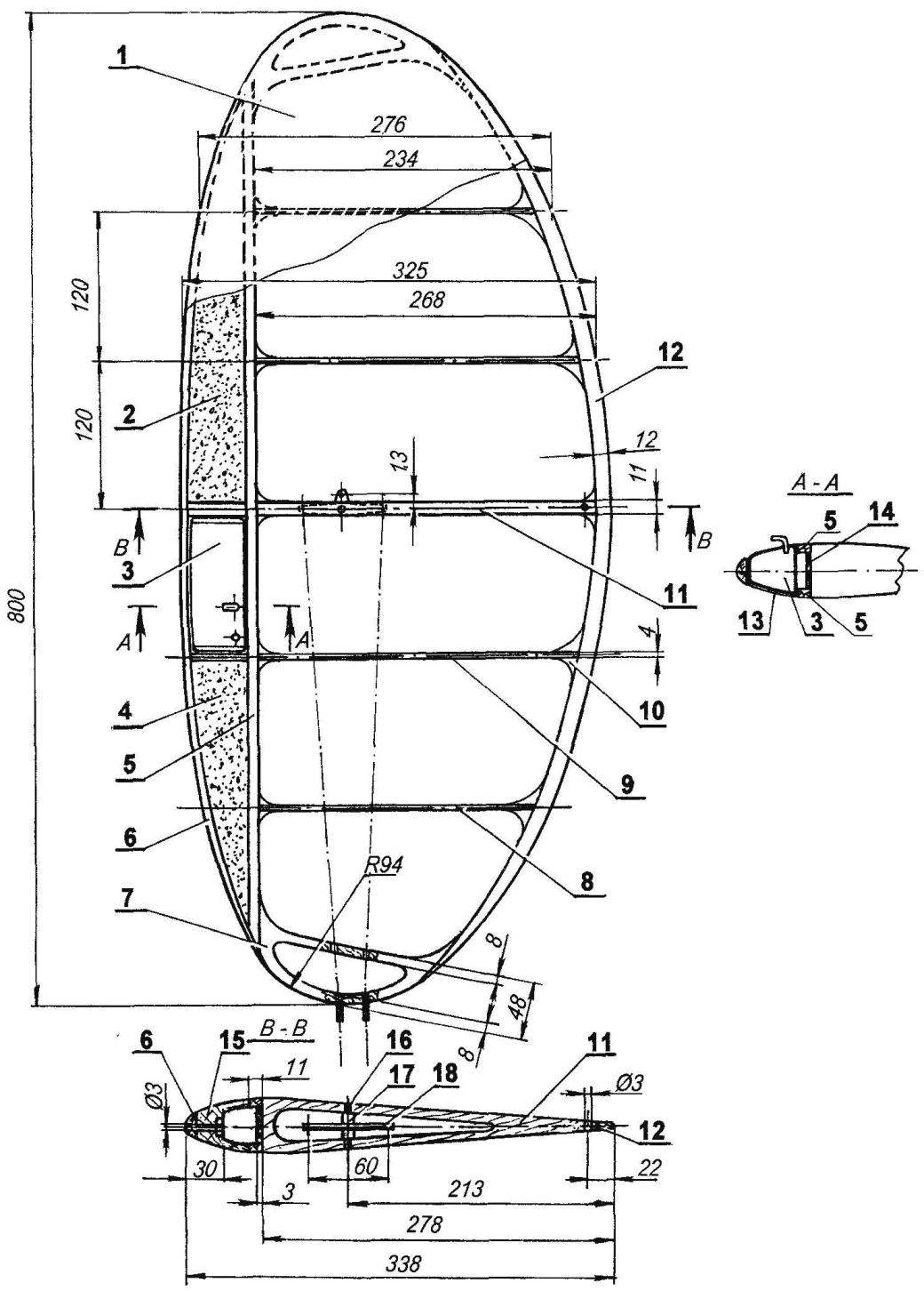
Wing:
1 — the wing (Mylar film); 2, 4 — foam filling the forehead of the wing; 3 — fuel tank (tinplate s0,3); 5 — beam flange (pine, rail 11×5); 6 — the leading edge (pine, rail 25×6); 7 — ending (plywood s5); 8 — rib No. 2 (school line s4); 9 — rib No. 1 (school line s4); 10 — enhancing scarf (lime); 11 — the Central rib (Linden, plate s11); 12 — rear flange (pine, rail 6×15); 13 — a lining tank compartment (Linden, veneer s1); 14 — the spar web (Linden, plate s3); 15 — strengthening of the forehead of the wing (Linden); 16 — axis of rocking of the control (steel, wire Ø3); 17 — remote bushing (PTFE); 18 rocking control (duralumin, sheet s3)
The Central rib is carved from lime plate 1 mm thick, on the inside it has a cut-out relief. External ribs (they also have a cut-ease) made of school rulers a thickness of 4 mm.
Front and rear edge of the wing is carved from pine slats to give them the curved shape of the wood reprisals in boiling water and laid in the stocks, which is a thick Board with scored it along the contours of the edges of nails with a thickness of 5 — 6 mm — each nail rake tied strong twine. Wingtips are cut from plywood with a thickness of 5 mm.
Wing Assembly was carried out to the slipway, made of plate DP 16 mm thick, on which was fastened a sheet of drawing paper with the picture of the planned projection of the wing.
Wing profile — type, P-52 (modified with thickened trailing edge), its relative thickness is 13 percent. Such a profile more suited for the “bouzouki” and “pilotage” — it has good bearing properties, and it provides a soft and smooth character stall that will simplify piloting.
The connection of the frame elements is carried out on the slipway with epoxy glue, if required, slightly diluted with acetone. The right wing tip with thread and glue attached lead weight with a mass of about 20 g.
Fuel tank, welded of sheet 0.3 mm thick, is placed between the Central and the first (counting from the plane of symmetry of the model) ribs and the right wing flush with the surface of the forehead. Wing tank compartment is open top and bottom sewn fake veneer. Carefully made from a tank will not introduce noticeable distortion in the flow around the wing, and to secure it in the wing need only strips of adhesive tape Scotch tape.
Rocking control cut from sheet duralumin of a thickness of 3 mm. it is Secured inside the Central rib with a steel axis with a thickness of 3 mm and a pair of remote bushings made from PTFE. The control cables passing inside the wing, formation of the folded in half cords. At the exit of the wing fixed bushings, springs with a length of about 30 mm. control rod connecting the rocking chair and horn all-moving stabilizer, made of aluminum knitting needles with a diameter of 3 mm.
The wing is covered with colored Mylar film model according to the classical technology with the use of glue “Moment” or BF-2 and electric iron. In the zone of passage of the control rod of the casing is attached via a “patch” of tape.
The fuselage of the model is flat, with a thickness of 11 mm. is He going to epoxy glue beech engine mounts and two plates of pine slats. The hole in the fuselage is made strictly according to the contour of the Central rib. With the wing the fuselage is connected by two bolts — one of them is passed through an engine mount, the other — through the strengthening of the trailing edge of the wing.
In the rear part of the fuselage fixed swivel stabilizer — it is a plastic tube with an inner diameter of 3 mm, which are inserted into two steel axles and operating at a compression coil spring.
Models stabilizer — all-moving. His power base is the frame sawed out of plywood with a thickness of 6 mm. After final processing of the frame cutouts in it are Packed with packing foam, and then upholstered in the surface of the Mylar film. The maximum deflection of the Elevator up and down should be about 30 degrees.
Aerobatic version of the model is additionally equipped with a keel, lantern and chassis. First it is best to make lime plate thickness of 5 mm and much better balsa.
The layout of the lantern of the cockpit is the easiest way to do contour, securing the fuselage bent according to the contours of the lamp dural needle with a diameter of 3 mm.
Landing gear is bent from wire, allied with a diameter of 4 mm at the top of each thread for fastening them with a pair of nuts glued to the rib No. 1 of the bosses, and the lower for fixing the wheels. As the latter is more convenient to use a plastic wheel with rubber tire children’s toys, their outer diameter should be about 40 mm. the Rear landing gear is bent from a wire OVS diameter 2 mm.
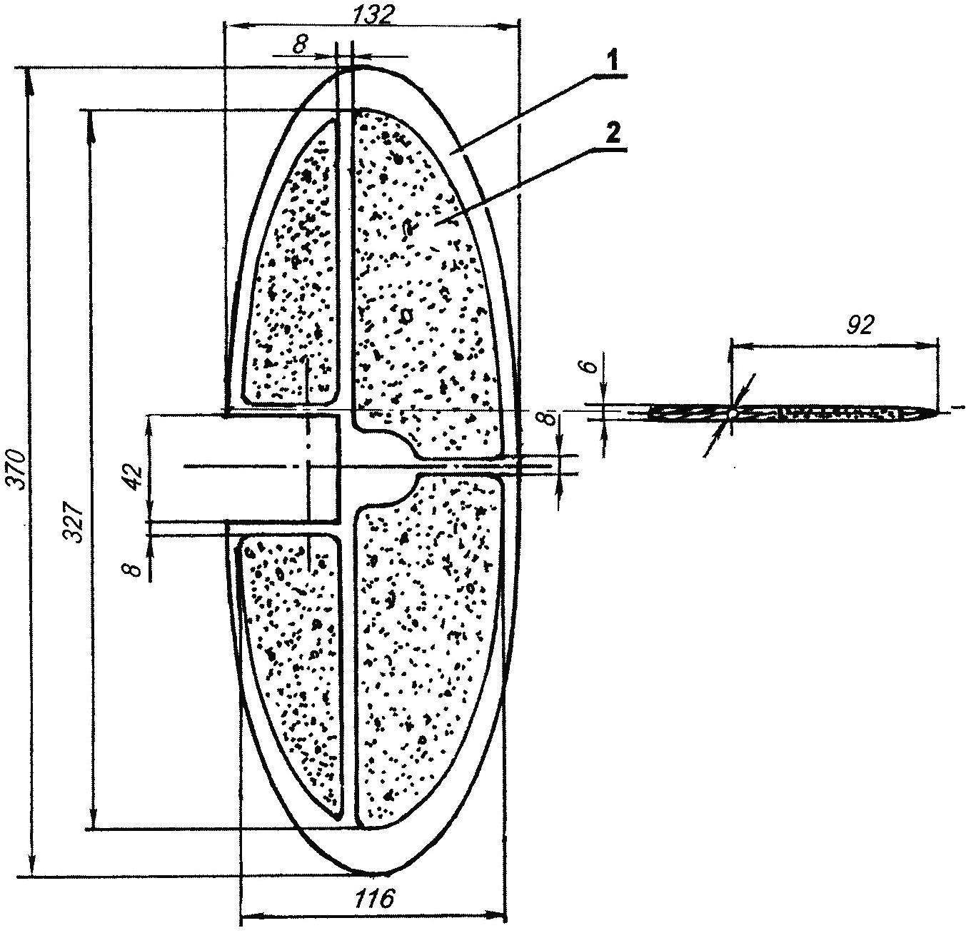
Stabilizer:
1 — frame (plywood s6); 2 — filling (foam)
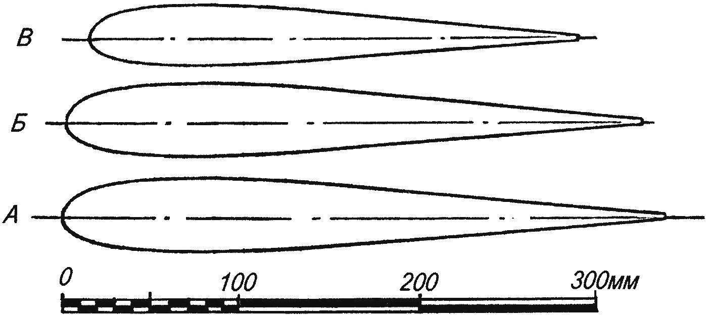
The control section of the wing on the ribs
A Central rib; B — on the rib No. 1; At the rib No. 2
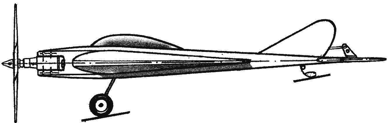
Aerobatic version of the model
After Assembly, the model must be adjusted correctly.
For our models the centre of gravity at the point corresponding to 15 — 20 percent of the chord of the wing (50 — 70 mm), measured from the front edge of the Central rib. By the way, the measurements of the position of the center of gravity should be performed several times in the Assembly process of the model, facilitating if necessary, certain elements of it.
If the alignment is likely to differ from the recommended, you can bring it back to normal with the help of cargo, securing it in the front or the rear of the fuselage.
For more experienced athletes the model’s center of gravity can be shifted back to 25 — 28 percent of the chord of the wing.
I. SOROKIN
Recommend to read
 THE GARDENER’S STOVE
In rural estate-type houses, and even in simple country cottages, of which there are countless numbers today, it's unlikely to get by without some kind of stove — Russian, Dutch, or a...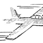 THE SILENCER IN THE MUFFLER
The problem of noise of operation of internal combustion engines exist in all types of modeling. The modelers of the upper boundary of the acceptable level of noise has long been...
